Utilizing iron-rich copper slag in high-iron portland cement preparation: effect of Fe-Al ratios on calcination, hydration and sulfate resistance
High-iron Portland cement (also known as high-ferrite cement, HFC), as a novel cement-based material, has emerged as an ideal choice for marine engineering due to its exceptional sulfate resistance, superior wear resistance, and enhanced frost resistance [1]. Compared with ordinary Portland cement (OPC), HFC reduces cumulative heat release by 29.3%, significantly alleviating thermal stress during the casting of mass concrete structures [2], while simultaneously improving wear resistance by 30% [3]. Crucially, HFC contains more than 18 wt.% of iron-phase components, providing robust resistance to Cl− and SO42− corrosion in seawater [4]. The unique performance advantages of HFC effectively address the durability limitations of OPC, offering a new solution to combat corrosion and aging issues in global marine infrastructures. However, current HFC formulations rely primarily on iron powder as the Fe-adjusting component, which necessitates the addition of mineralizers such as calcium fluoride, calcium sulfate, and zinc sulfate to reduce the calcination temperature and promote mineral-phase formation [5, 6]. The effects of these mineralizers during the sintering process are complex and difficult to control, and they also increase calcination costs. Therefore, there is a need to identify a sustainable alternative to iron powder.
Copper slag, an industrial by-product of copper smelting, contains 40–50% iron and 25–35% silica. It dominantly consists of low-melting-point glassy phase FeSiO3, which can reduce the clinker calcination temperature and delay the formation of the burning zone even in the absence of mineralizers, making it a promising raw material for producing HFC [7]. In 2023, approximately 49.06 million tons of copper slag were directly stockpiled worldwide [8], and improper disposal can lead to the leaching of heavy metals into soil and groundwater, causing severe environmental hazards. Currently, copper slag is primarily utilized as a supplementary cementitious material to partially substitute cement. Studies indicate that when the replacement ratio is between 5% and 10%, concrete achieves optimal compressive and flexural strengths [9], and copper slag exhibits higher reactivity and volumetric stability than fly ash [10]. When employed as coarse aggregate, copper slag can increase the compressive strength of concrete by 40% and its tensile and flexural strengths by 60% [11]; when used as fine aggregate, it can reduce chloride-ion permeability by 38% [12]. Despite these advantages, the use of copper slag in concrete largely remains limited to its role as a filler, leaving its chemical potential in the slag melting process underutilized. Furthermore, copper slag contains heavy metals such as Cu2+, Cr3+, and Mn2+ [13], which are susceptible to secondary leaching, complicating stabilization and presenting environmental and safety risks [14–16]. Therefore, using copper slag as the iron-phase precursor for HFC calcination not only enables the immobilization of hazardous heavy metals through high-temperature incorporation into mineral lattices [17], but also allows the inherent chemistry of the slag to optimize the HFC clinker mineral system, thereby achieving high-value utilization of copper slag.
Iron-phase content significantly affects the mineral composition, hydration behavior, and sulfate resistance [18]. An increase in C4AF reduces the C3S content, and at high iron-phase fractions the proportion of C3A may rise slightly [19]. Chabayashi et al. [20] reported that as iron-phase content increases, C3S decreases while Al2O3 precipitates during calcination to form C3A; once C4AF exceeds a certain proportion, additional release of Al2O3 leads to a modest increase in C3A, thereby affecting the performance of the cement. Schade et al. [21] showed that high iron content promotes AFm formation and enhances compressive strength, whereas lower iron content facilitates the formation of C-S-H. In sulfate environments, C4AF hydration is altered, which in turn affects sulfate resistance of cement. Huang et al. [22] found that sulfates accelerate C4AF hydration and, in the presence of gypsum, yield AFt and amorphous Al(OH)3. However, Ye et al. [23] observed that sulfate solutions inhibit the hydration of C4AF, with calcium sulfate (CaSO4) exerting the strongest inhibition and sodium sulfate (Na2SO4) the weakest. Given that copper slag is iron-rich, using it as a raw material for HFC calcination can markedly affect mineral composition, cement hydration, and the sulfate resistance of cement. However, to date, there are limited comprehensive studies that address this gap of understanding.
In this study, a series of high-iron Portland cements (HFC) with varying Fe-Al ratios were designed. The effects of different Fe-Al ratios and calcination systems on the formation, burnability and grindability of clinker minerals were investigated using measurements of linear shrinkage, free calcium oxide (f-CaO) content, X-ray diffraction (XRD), specific surface area and particle size distribution. In addition, heat of hydration, XRD, and scanning electron microscopy (SEM) were employed to reveal the regulation mechanisms of copper slag on the hydration process and sulfate resistance. The mechanical properties of the HFC were evaluated, and the calcination process and mechanisms of sulfate resistance in HFC produced from copper slag were clarified. This work thus provides a new pathway for the high-value and environmentally safe utilization of copper slag in sulfate-resistant, low-heat cements suitable for marine engineering and other demanding environments.
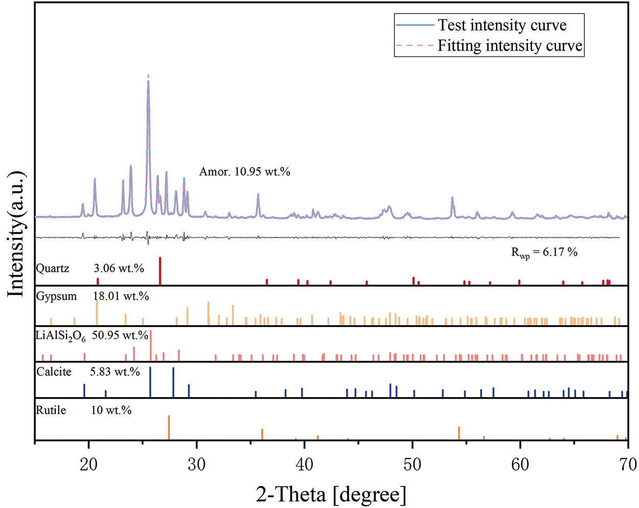
Copper slag (provided by China Copper Southeast Copper Industry Co., Ltd., Fujian, China) was calcined at 900°C, resulting in a density and specific surface area of 2.7 g/cm3 and 11,460 cm2/g, respectively. The chemical composition of the copper slag was characterized by XRD (Table 1 and Figure 1a), and its microstructure was examined by SEM (Figure 1b). The raw materials for cement production were obtained from the cement plant, with their chemical composition and microstructure detailed in Table 1 and Figure 2, respectively. The sand used in this study was standard sand with a particle size of 0.5 mm–1.0 mm.
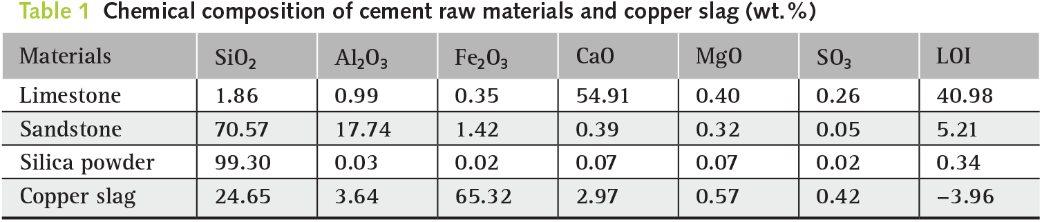
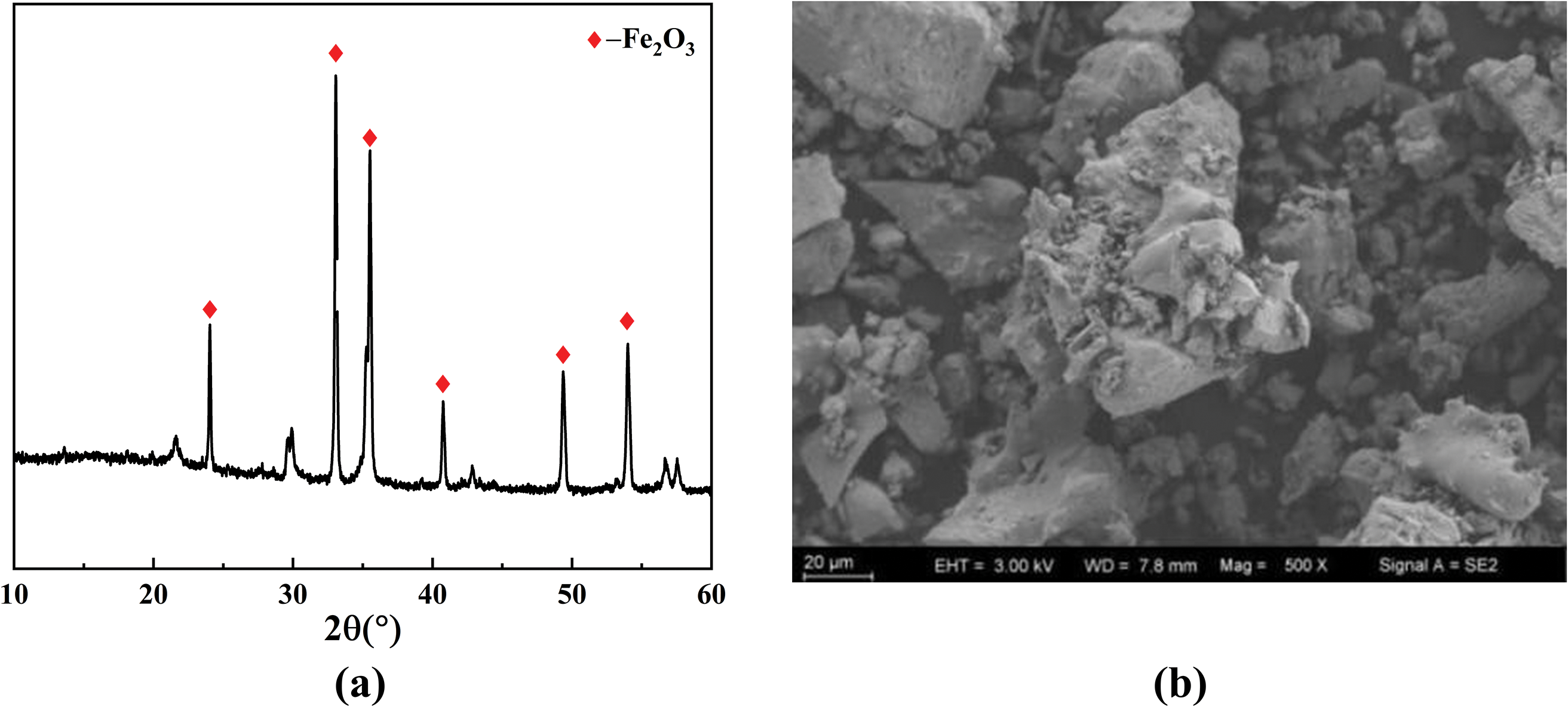
Figure 1 Copper slag properties: (a) XRD and (b) SEM
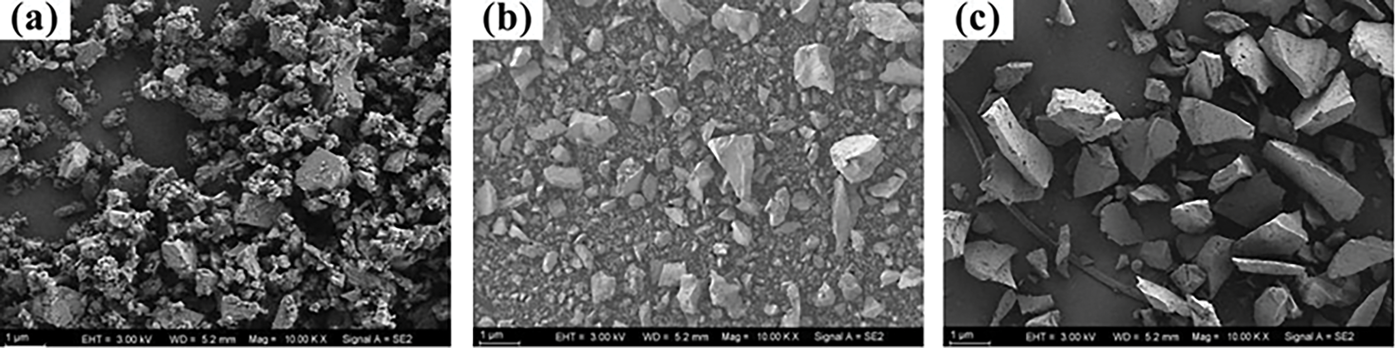
Figure 2 Morphology of: (a) limestone, (b) sandstone and (c) silica powder
2.2 Preparation of cement clinker
Raw material pretreatment: Limestone, sandstone, silica powder, and copper slag were first crushed and refined using a jaw crusher and high-speed pulverizer, then finely ground in a horizontal ball mill and sieved through a 200-mesh sieve, with the residue rate controlled to around 10%. The materials were then dried in an oven at 105°C for at least 60 min to ensure the moisture content met the experimental requirements. After treatment, all samples were placed in a desiccator to cool for further use.
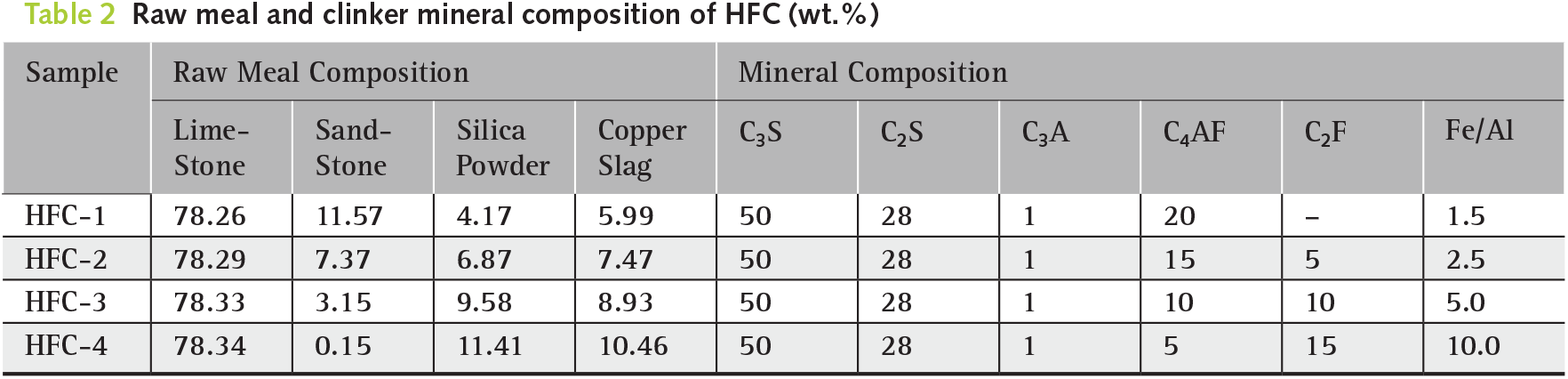
Preparation of cement raw meal: The raw materials were first placed in a WZM horizontal ball mill and mixed uniformly for 30 min at a speed of 20 r/min, according to the raw meal composition (Table 2). Next, 10 wt.% deionized water (by weight of raw materials) was added and thoroughly stirred to ensure complete binding of the materials. The resulting mixture was then compressed into raw meal cakes, each with a diameter of 50 mm and a weight of approximately 50 g, using a mold. Finally, the raw meal cakes were dried in an oven at 90°C for at least 1 h to remove moisture, ensuring optimal molding stability.
Preparation of cement clinker: The raw meal cakes were placed in a crucible and calcined in a high-temperature muffle furnace. The furnace was heated at a rate of 10°C/min, and once the target temperature was reached, the samples were maintained at that temperature for 40 min to ensure complete clinkerization of the cement minerals. After calcination, the cement clinker was immediately removed from the furnace and rapidly cooled in front of an AC unit blowing cool air (12 ± 3°C) to prevent disintegration due to annealing.
Preparation of cement: The cooled clinker blocks were then crushed and pretreated using a hydraulic disk and high-speed pulverizer, resulting in clinker particles with a diameter of ≤2 mm. These particles were then mixed with gypsum and steel balls in a steel container at a specified mass ratio for grinding. Finally, HFC samples were obtained by sieving through 200-mesh and 300-mesh sieves, respectively. The preparation schematic is shown in Figure 3.
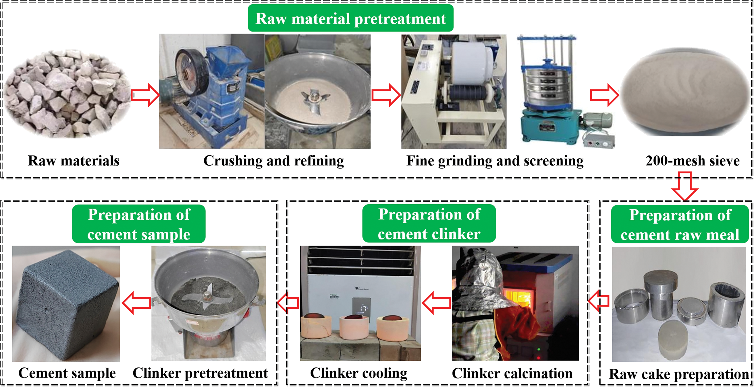
Figure 3 Preparation schematic diagram of copper slag cement
To improve the utilization of copper slag and increase the iron content, this study maintains constant levels of C3S, C2S, and C3A while varying the Fe2O3 and Al2O3 contents in the chemical compositions of C4AF and C2F. Cement clinkers with Fe-Al ratios of 1.5, 2.5, 5.0, and 10.0 were designed, defined as HFC-1, HFC-2, HFC-3, and HFC-4, respectively. The calculated mineral compositions of HFC are provided in Table 2.
The diameters of the upper and lower surfaces of the raw meal cake were measured using a vernier scale. After calcination, the linear dimensions of the diameters of the upper and lower surfaces of the clinker were measured. The average values were then used to calculate the linear shrinkage rate and investigate the dimensional shrinkage effects of the raw meal at different calcination temperatures.
2.3.2 Determination of free lime
The f-CaO content in cement clinker was quantitatively determined using the ethylene glycol method [24]. First, an indicator solution was prepared by mixing methyl red, bromocresol green, anhydrous ethanol, and ethylene glycol. Calcium carbonate (CaCO3) was then calcined in a muffle furnace at 950°C until it reached constant weight, yielding CaO. The indicator solution was added to the CaO, and the mixture was heated and stirred at 70°C for 30 min. The solid phase was removed by vacuum filtration, and the residue was washed three times with anhydrous ethanol. The filtrate was subsequently titrated with a 1 mol/L hydrochloric acid (HCl) standard solution. The volume of HCl consumed was recorded when the solution changed color from blue to orange. Finally, the clinker was treated and titrated under the same conditions, and the volume of HCl consumed was recorded. The f-CaO content was calculated using Equations (1) and (2).
Standard sand with a density of 1.40 g/cm3 and a particle size of 0.3 mm–1.0 mm, along with clinker, were selected as samples and placed in a Φ300 mm × 300 mm WZM horizontal ball mill. Grinding was performed at a speed of 70 r/min for 20, 30, 40, 50, and 60 min, with samples collected every 10 min. The specific surface area of the samples was subsequently measured using a TriStar II 3020 automatic specific surface area analyzer (Micromerics Inc., Norcross, GA, USA). The grindability coefficient (K1) of the clinker was calculated using Equation (3).
where S was the specific surface area of the clinker, and Ss was the specific surface area of the standard sand.
2.3.4 Particle size distribution of cement
The particle size distribution of cement was conducted through a Malvern Mastersize 2000 analyzer (Malvern Instruments, Ltd., Malvern, UK). A cement paste was prepared with a w/c of 0.40, and then the paste was diluted 20 times for testing.
The mineral composition of the clinker and hydration products of the cement were identified using a SmartLab SE X-ray diffractometer (Rigaku, Tokyo, Japan) with CuKα radiation. Scans were performed for a 2θ range of 5°–90°, a step size of 0.01°, and a scanning speed of 2°/min. The electron beam and voltage were 100 mA and 40 kV, respectively.
The composition analysis of the hydration products of the HFC pastes under sulfate attack at 7 d and 28 d of curing was conducted using the methods and testing conditions described above. After reaching the designated curing ages, the pastes were immersed in isopropanol to terminate hydration, followed by vacuum drying, grinding, and sieving through a 200-mesh sieve to obtain the samples for analysis.
The heat of hydration of the cement pastes was measured using a TAM AIR isothermal calorimeter (TA Instruments, New Castle, DE, USA), with a w/c of 0.40 to prepare the cement paste samples. The heat releases of the pastes were recorded at a constant temperature of 23°C for 168 h.
2.3.7 Scanning electron microscope
A GeminiSEM 300 (Carl Zeiss, Oberkochen, Germany) was used for morphological observation of the cement. Samples were subsequently immersed in isopropanol to terminate the hydration.
The compressive and flexural strengths of the cement pastes were tested according to GB/T 17671-2021 [25], with the average strength calculated from six samples. The cement pastes, with a w/c of 0.40, were thoroughly mixed and poured into a mold with the size of 40 mm × 40 mm × 160 mm. After curing for 1 d in a standard curing box ((20 ± 2)°C, relative humidity ≥95%), the specimens were demolded and returned to the curing box for further curing until the specified age. The strengths of the paste were tested at 3, 7, and 28 d.
The sulfate resistance of the HFC was determined using the K-value method according to GB/T 749-2008 [26]. The cement, standard sand, and water were mixed in a mass ratio of 1.0:2.5:0.5. The thoroughly mixed mortar was poured into molds measuring 10 mm × 10 mm × 60 mm. After curing for 1 d in a standard curing box, the specimens were demolded and transferred to a constant temperature water bath at (50 ± 1)°C for continuous curing for 7 d. The samples were then immersed in a 3 wt.% Na2SO4 solution and deionized water at (20 ± 1)°C until 28 d, after which their flexural strength was tested. The sulfate resistance coefficient (K2) was calculated using Equation (4).
where Rs was the flexural strength of the mortar in a 3 wt.% Na2SO4 solution (MPa), and Rw was the flexural strength of the mortar in water solution (MPa).
The burnability of the clinker was tested at calcination temperatures of 1330°C, 1360°C, 1390°C, 1420°C, 1450°C, and 1480°C. The results are shown in Figure 4.
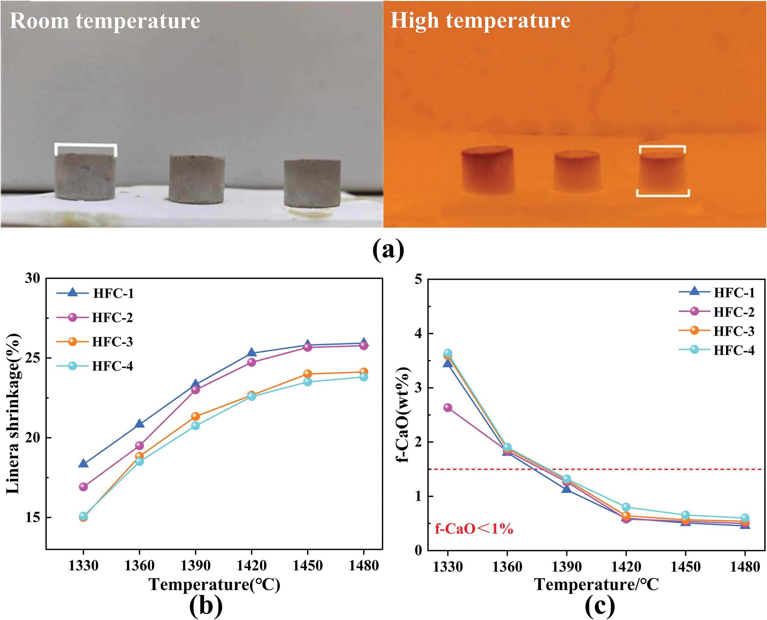
Figure 4 Burnability of cement clinker: (a) calcination process, (b) shrinkage and (c) f-CaO content
The linear shrinkage of the cement clinker was calculated based on Figure 4a. From Figure 4b, with increasing calcination temperature, the linear shrinkage of clinkers with different ratios exhibited an upward trend and tended to stabilize within the temperature range of 1420°C–1480°C, indicating that calcination was nearly completed at 1420°C. The linear shrinkage of HFC-2, HFC-3, and HFC-4 was lower than that of HFC-1 clinker, with HFC-3 and HFC-4 showing the most significant decrease. At 1480°C, the linear shrinkage of HFC-3 and HFC-4 was 24.12% and 23.83%, respectively, about 2% lower than that of HFC-1. This suggests that increasing the Fe-Al ratio in the iron phase does not significantly enhance the clinker’s linear shrinkage, and the addition of copper slag has limited effects on improving the densification during firing.
From Figure 4b, with increasing calcination temperature, the f-CaO content of the clinker gradually decreased. However, as the Fe-Al ratio increased, the f-CaO content at the same calcination temperature did not further decrease. Using f-CaO < 1.5 wt.% as the baseline, the required temperatures for HFC-2, HFC-3, and HFC-4 were higher than that for HFC-1, indicating that HFC-2, HFC-3, and HFC-4 gradually shifted from C4AF to C2F. The increased copper slag content did not further improve the clinker’s linear shrinkage. Furthermore, at the same calcination temperature, the f-CaO contents of these mixtures did not differ significantly from that of HFC-1. These results indicate that the addition of copper slag has a limited effect on improving the clinker burnability, and excessive addition does not cause issues such as overburning or significant viscosity drop.
To further investigate the effect of Fe-Al ratio in iron-phase minerals on clinker calcination temperature, the theoretical liquid phase P value at different firing temperatures was calculated according to reference [27, 28]. The results are shown in Table 3.
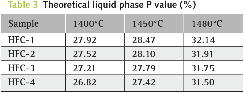
During the cement calcination process, C2S required a certain amount of liquid phase to dissolve and absorb CaO for the formation of C3S. Therefore, the liquid phase content of cement clinker during firing needs to be maintained within the range of 20%–30% [29, 30]. From Table 3, with an increase in calcination temperature from 1400°C to 1480°C, the liquid phase P value of all cement clinkers increased. However, as the Fe-Al ratio increased, the P value gradually decreased, with HFC-4 exhibiting the lowest value. This indicates that a higher Fe-Al ratio reduces the formation of the liquid phase, which also explains the lower f-CaO content in HFC-1. Furthermore, except at 1480°C, the liquid phase content of HFC-1 to HFC-4 remained within the optimal range for cement clinker calcination. Higher Fe-Al ratio means higher copper slag content, which is beneficial for solid waste utilization.
Based on the above results, 1390°C is the suitable calcination temperature for HFC-1~4 in this study, as it is associated with relatively low linear shrinkage and f-CaO content. This calcination temperature is significantly lower than 1450°C of ordinary Portland cement [30, 31], leading to a reduction in energy consumption by 17.0%–20.3% and CO2 emissions by 15.0%–18.6% [5].
The mineral composition of the clinker, determined by XRD, is shown in Figure 5. The main phases of the HFC clinker were C3S and C2S, along with various iron-rich phases. No impurities were detected in the XRD spectra (see Figure 5), indicating that changes in the iron-phase composition did not affect the overall mineral phase composition. Furthermore, as the Fe-Al ratio increased, the characteristic peaks of the iron phases shifted to lower angles, primarily due to an increase in interplanar spacing (d-value). This shift corresponded to a transition from C4AF (higher Al2O3 content) to C2F (higher Fe2O3 content). These phase changes were consistent with the theoretical design of the iron-phase solid solution composition, suggesting that the Fe-Al ratio played a directional role in regulating the crystal structure of iron-phase minerals.
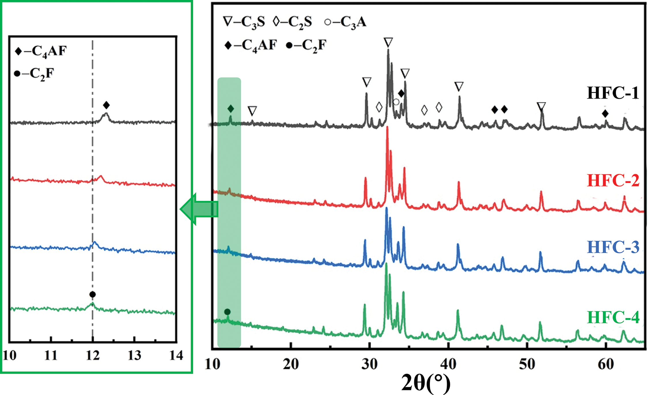
Figure 5 XRD spectrum of HFC clinker
To further investigate the actual mineral content in the clinker, a Rietveld quantitative analysis of the HFC was conducted using XRD, and the results are shown in Figure 6. In addition, the chemical compositions of the clinker were determined using an X-ray fluorescence (XRF) analyzer, and the results are displayed inTable 4.
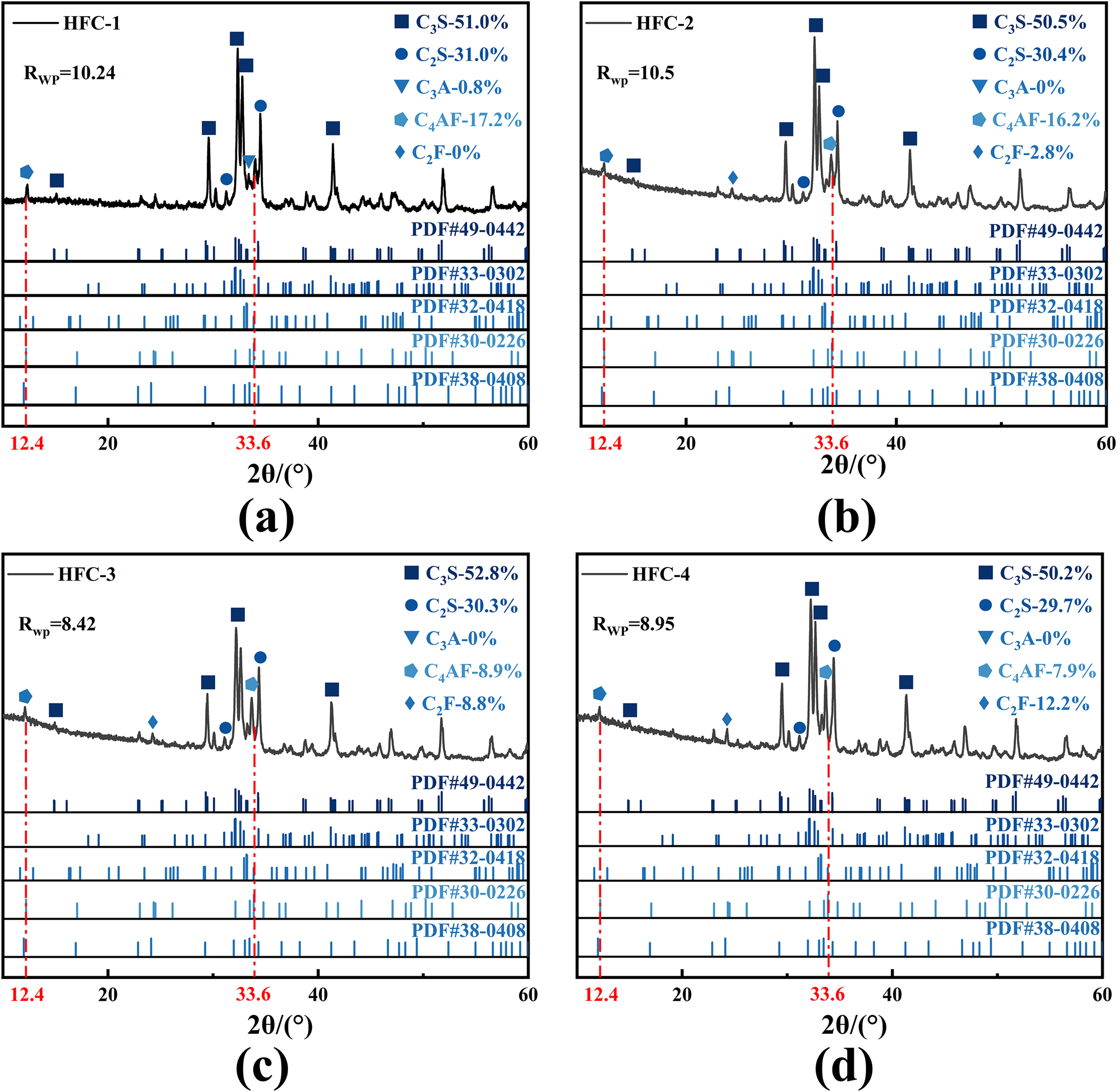
Figure 6 Rietveld quantitative analysis of: (a) HFC-1; (b) HFC-2; (c) HFC-3 and (d) HFC-4
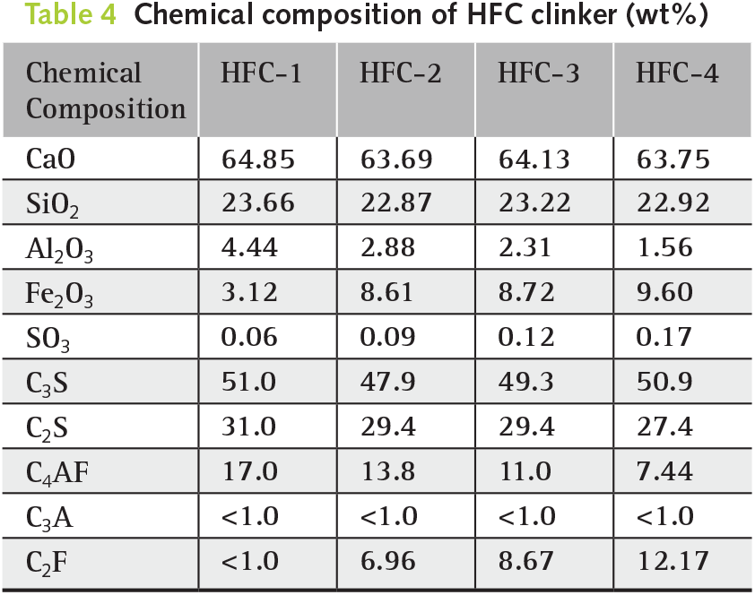
From Figure 6 and Table 4, the chemical composition closely matched the design values, with an error of less than 3% and a variance factor (Rwp) value under 15%, indicating that the cement preparation was consistent with the theoretical design. Furthermore, compared with HFC-1, as the Al2O3 content decreased, HFC-2 to HFC-4 did not form C3A minerals. In these cases, the iron phases in the clinker mainly consisted of C4AF and C2F. This suggests that higher Fe2O3 content reacts with C3A to form C4AF, reducing the C3A mineral content, while the remaining iron combines with calcium to form C2F mineral crystals. Also from Table 4, it can be observed that the CaO content remained around 64% in all samples, indicating that variations in the Fe-Al ratio had little impact on clinker burnability, which is consistent with the results of the cement burnability tests. Therefore, at a calcination temperature of 1390°C, high-iron Portland cement with different Fe-Al ratios can be produced using copper slag, which meets the experimental design requirements.
To investigate the impact of different Fe-Al ratios on the grindability of cement clinker, grindability tests were conducted using standard sand as a reference. The results are presented in Figure 7 and Table 5.
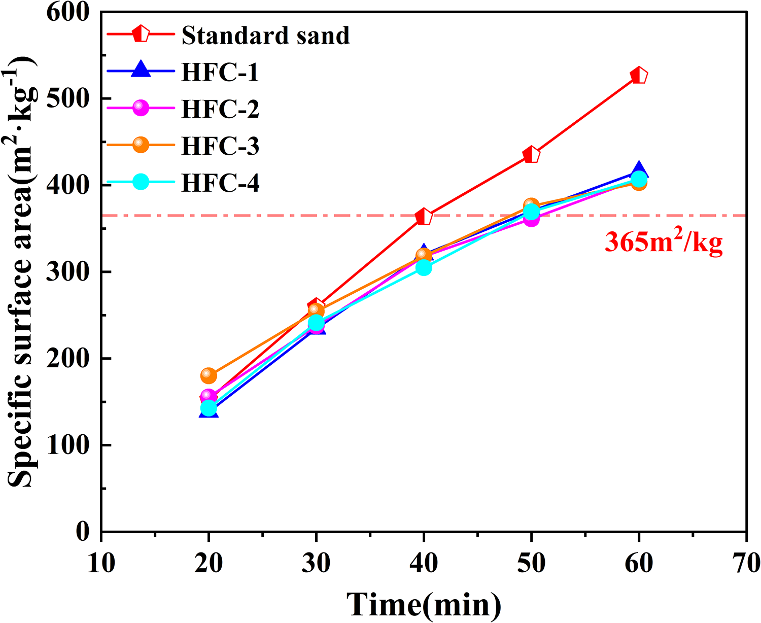
Figure 7 Grindability of cement clinker
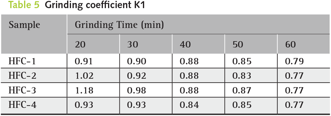
From Figure 7, the specific surface area of cement clinkers with different Fe-Al ratios increased with grinding time. Although the values across sample were relatively similar, they consistently remained lower than that of standard sand. From Table 5, at the early stage of grinding (20 min), the K1 values for HFC-2 and HFC-3 clinkers were greater than 1, indicating superior grindability compared with standard sand. As the grinding time increased, the K1 values for HFC-1 to HFC-4 clinkers gradually decreased and fell below 1, at which point the clinkers had a smaller specific surface area and lower grindability than standard sand. Importantly, all samples reached a specific surface area of 365 m2/kg after approximately 50 min, indicating that variations in the Fe-Al ratio had little effect on the final grinding efficiency of the HFC clinkers. This finding suggests that increasing copper slag content does not negatively impact grinding performance during cement production; similarly, higher copper slag content is desirable in terms of solid waste utilization.
Based on the grindability results, the clinker was mixed with 5% gypsum and ground to a specific surface area of 365 ± 5 m2/kg. The cement samples were then obtained by sieving the ground material through a 300-mesh sieve, and the particle size distribution is shown in Figure 8.
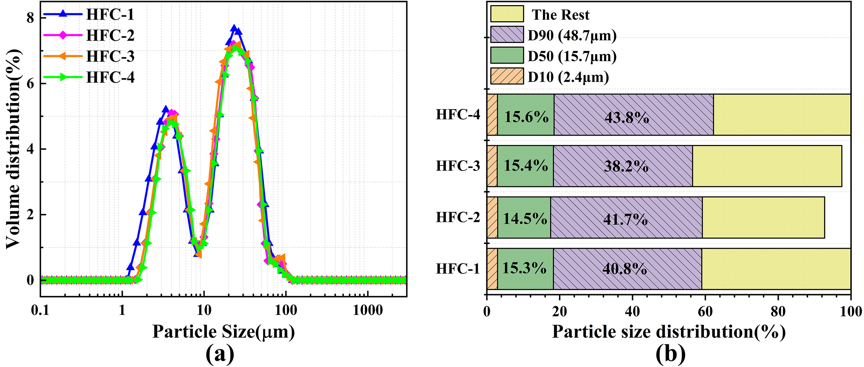
Figure 8 Particle size of HFC: (a) distribution curves and (b) characteristic values
From Figure 8, the particle size distributions of the HFC samples were similar, with the majority of particles ranging from 15.7 μm to 48.7 μm, indicating minimal differences in particle size among the cement samples. This was in line with the requirements for cement particle size and hydration performance [32]. The uniform particle size distribution provided a reliable foundation for subsequent cement experiments and eliminated any potential influence of particle size on the experimental results.
3.2 Mechanical properties of cement pastes
The mechanical properties of the HFC pastes at 3, 7, and 28 d are shown in Figure 9. From Figure 9a, compared with the HFC-1 pastes, the compressive strength of the HFC-2, HFC-3, and HFC-4 pastes decreased significantly, with the decline becoming more pronounced as the Fe-Al ratio increased. Specifically, the compressive strength at 28 d decreased by 15.7%, 22.2%, and 22.6%, respectively. This is mainly due to the increase in the Fe-Al ratio, which caused the gradual conversion of C4AF to C2F, resulting in C2F becoming the dominant iron-phase mineral and consequently reducing strength. Furthermore, the C3A content in HFC-2 to HFC-4 was nearly zero (as shown in Table 4), indicating that the raw meal lacked sufficient Al elements to form C4AF and C3A, thereby promoting the predominant formation of C2F. Previous studies have confirmed that the iron-phase minerals in cement are mainly composed of C4AF, and reducing the proportion of C2F has a positive effect on improving the strength of cement pastes [33, 34]. From Figure 9b, the flexural strength of the cement pastes followed a similar trend to that of the compressive strength. The flexural strength at 28 d of the HFC-1 paste was 14.3 MPa, higher than the 12.9 MPa, 12.3 MPa, and 12.2 MPa of the HFC-2, HFC-3, and HFC-4 pastes, respectively.
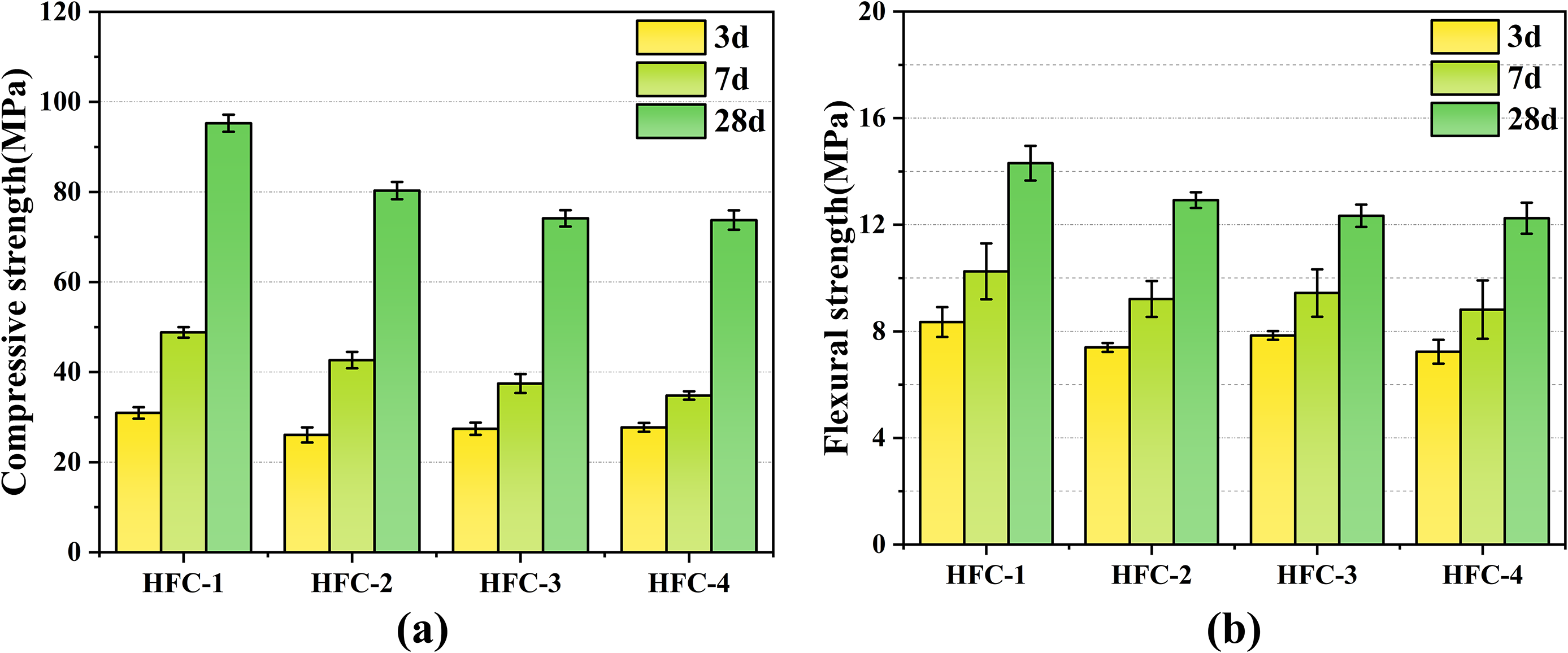
Figure 9 Mechanical properties of HFC pastes: (a) compressive strength and (b) flexural strength
According to GB/T 200-2025 [35], the compressive strength at 7 d and 28 d should exceed 13.0 MPa and 42.5 MPa, respectively, while the flexural strength should exceed 3.5 MPa and 6.5 MPa. Although the strength of the HFC-1 to HFC-4 pastes decreased with increasing Fe-Al ratio, they still exhibited excellent mechanical properties and met the technical requirements specified in GB/T 200-2025 [35]. These results indicate that solid waste copper slag can be utilized as an iron-bearing raw material in cement production, offering considerable potential for engineering applications and environmental benefits.
3.3 Hydration of cement pastes
The hydration test results of the cement with varying Fe-Al ratios are shown in Figure 10. Table 6 provides the hydration characteristic values of HFC pastes.
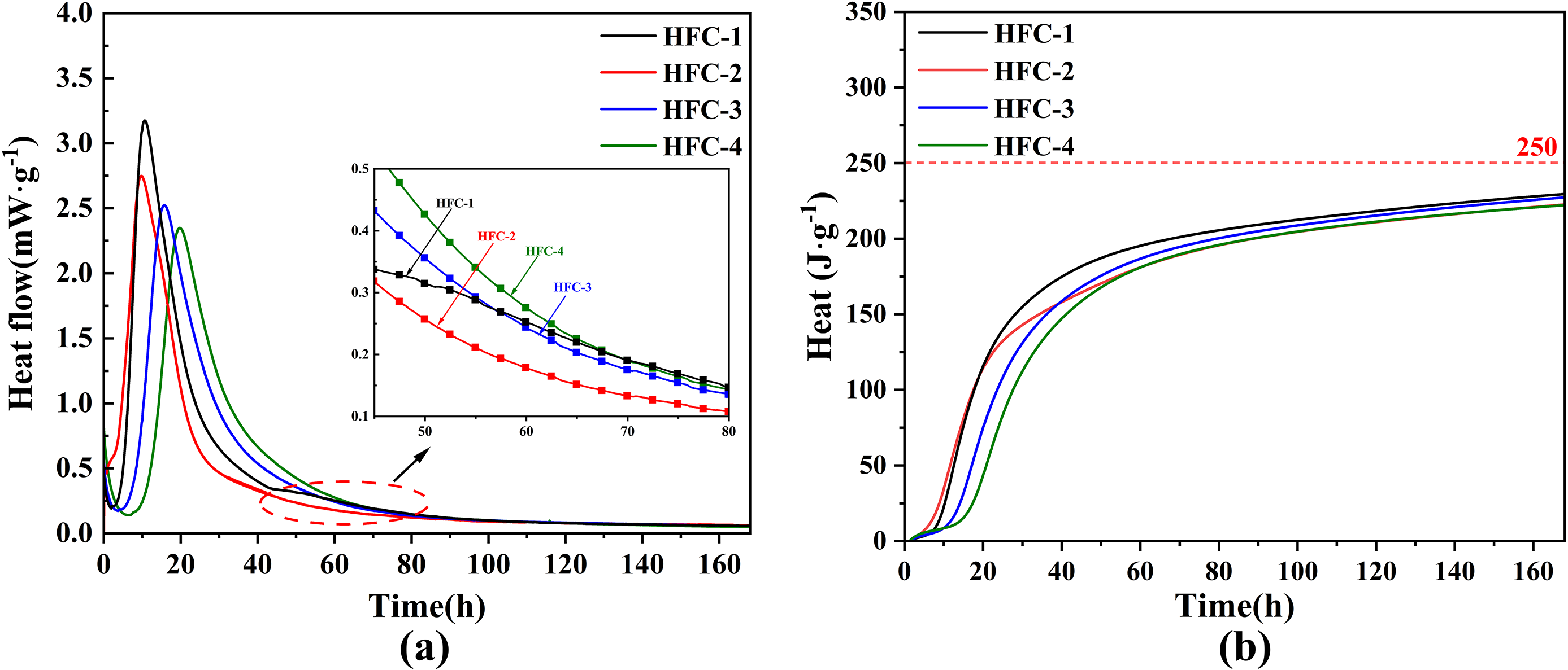
Figure 10 Hydration curves of HFC pastes: (a) heat flow and (b) cumulative heat release
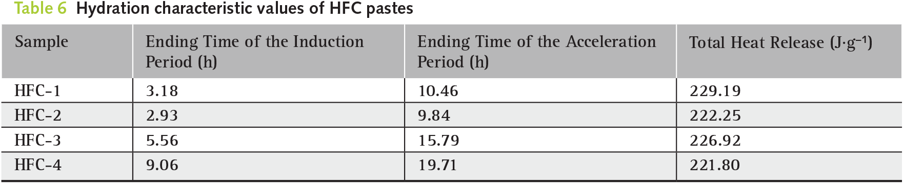
From Figure 10, the hydration heat release rate and total hydration heat of the HFC pastes with varying Fe-Al ratios exhibited significant differences. Based on the heat release rate curve (Figure 10a) and the hydration characteristic values (Table 6), the end times of the hydration induction and acceleration periods for the HFC-3 paste were 5.56 h and 15.79 h, respectively, while those for the HFC-4 paste were 9.06 h and 19.71 h, which were 3.18 h and 10.46 h longer than those of the HFC-1 paste. This indicates that the hydration reactivity of HFC-3 and HFC-4 is lower than that of HFC-1, exhibiting a notable retardation effect. This is primarily due to the increased Fe-Al ratio in the cement, which reduces the reactivity of C3S hydration, inhibits the formation of C3A, and promotes the conversion of C4AF to C2F, thus delaying the induction and acceleration periods. It can also be seen from Figure 10a that a small characteristic peak appeared around 52 h for the HFC-1 paste, which results from the accelerated hydration of the C4AF phase in HFC-1. In contrast, for HFC-2 to HFC-4, where the dominant iron phase is C2F, the degree of hydration is notably reduced.
As shown in Figure 10b and Table 6, the heat releases of the HFC-2, HFC-3, and HFC-4 pastes were 222.25 J·g−1, 226.92 J·g−1, and 221.80 J·g−1, respectively, all of which were lower than that of the HFC-1 paste. This further suggests that increasing the Fe-Al ratio reduces the hydration reaction of the cement. Although the hydration induction and acceleration periods of HFC-2 paste were similar to those of the HFC-1 paste, its overall heat release remained lower, indicating a retardation effect on hydration. Furthermore, the hydration heat release of all samples did not exceed 220 J·g−1 at 3 d and 250 J·g−1 at 7 d. which complies with the requirements of GB/T 200-2025 [35]. The heat release of HFC-3 increased rapidly during the 3 d, but subsequently leveled off to resemble that of the HFC-2 and HFC-4 pastes. This suggests that an increase in the Fe-Al ratio has a minimal effect on the total heat release, and the overall hydration heat evolution remains balanced.
The XRD spectra of HFC pastes at 28 d are showed in Figure 11.
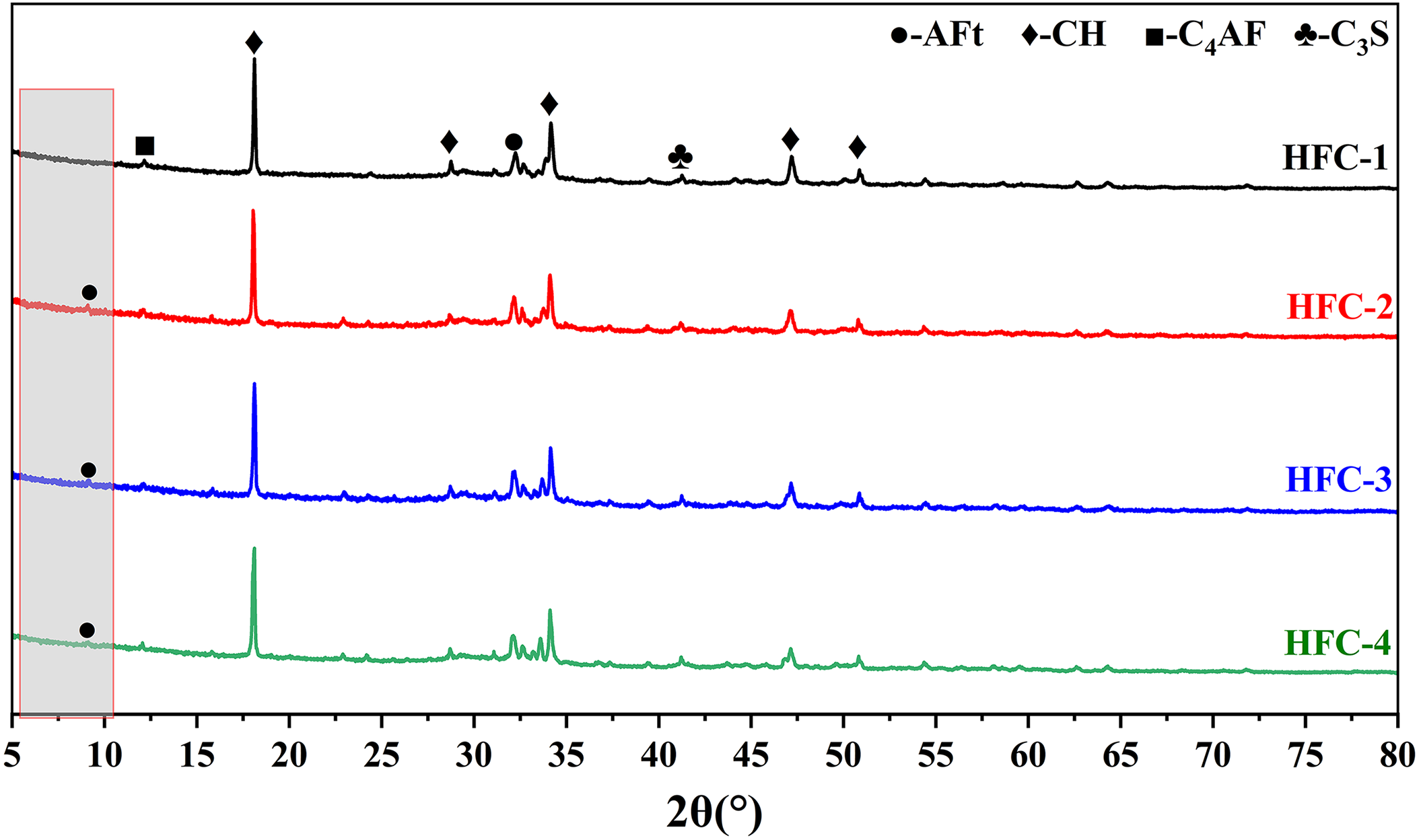
Figure 11 XRD spectrum of HFC pastes
As shown in Figure 11, increasing the Fe-Al ratio did not significantly alter the composition of the cement hydration products, which mainly included CH and AFt. Compared with the HFC-1 paste, the HFC-2, HFC-3, and HFC-4 pastes exhibited an AFt peak around 9.1°, with no AFm peak detected. This suggests that a higher proportion of iron phases contributes to AFt stability and prevents its transformation into AFm. From the CH peak at 18°, it can be found that the CH content in the HFC-4 paste decreased by 10% compared with the HFC-1 paste, indicating that further increases in the iron phase do not enhance the reactivity of calcium silicates, thereby resulting in a reduced degree of hydration. Additionally, as shown in Figure 11, no distinct gypsum peaks were detected during the hydration of the HFC pastes at 28 d. This may be attributed to the lower sulfate content in the cement, which led to the complete consumption of gypsum during hydration.
3.4.1 Effect on mechanical properties
The sulfate resistance of the HFC samples was tested, and Figure 12 shows the flexural strength and coefficient K2 of mortar specimens after 28 d of curing in water and the sulfate solution.
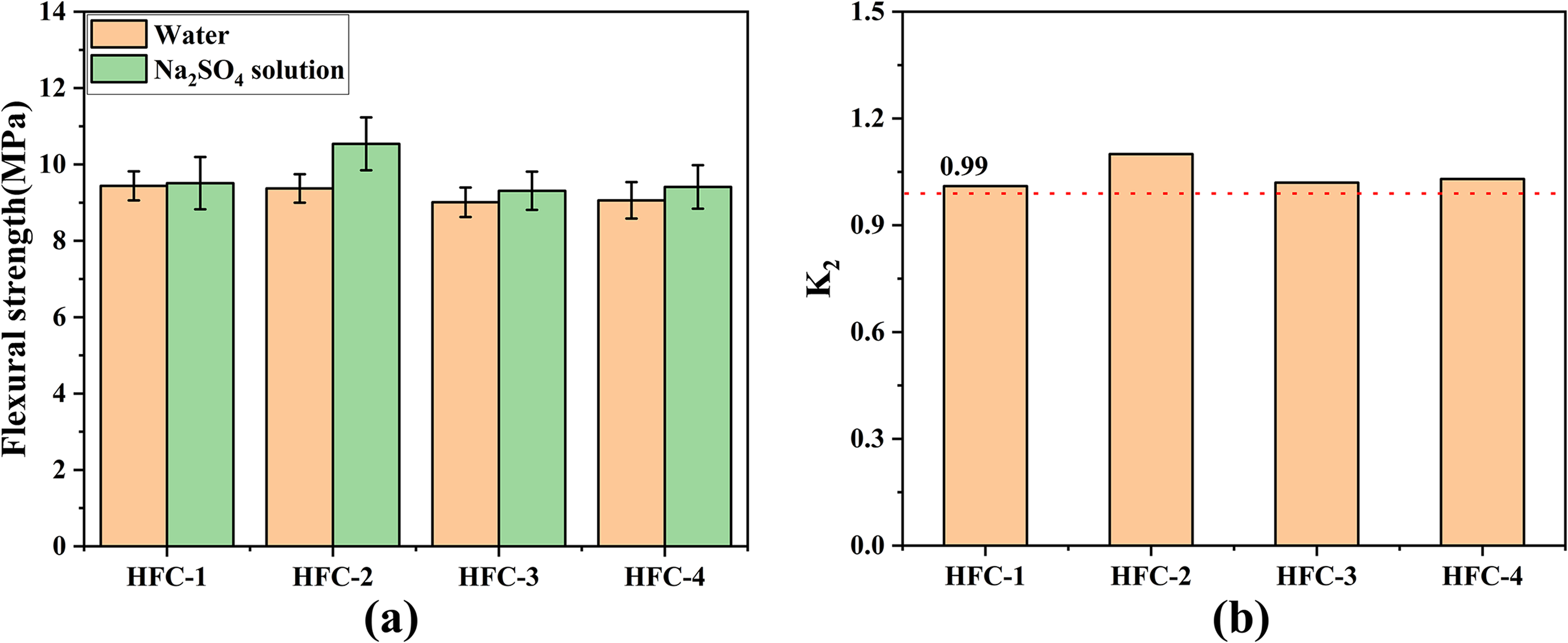
Figure 12 Sulfate resistance performance of mortar at 28 d: (a) flexural strength and (b) coefficient K2
From Figure 12a, the flexural strength of the HFC pastes cured in water decreased with increasing Fe-Al ratio, which was consistent with the trend observed in Figure 9b. In contrast, when the pastes were cured in the sulfate solution, a higher Fe-Al ratio led to an increase in flexural strength. Compared with water curing, the flexural strength of the HFC-1, HFC-2, HFC-3, and HFC-4 pastes increased by 0.74%, 12.48%, 3.33%, and 3.86%, respectively, under sulfate solution curing. As shown in Figure 12b, the K2 values of the HFC-2 to HFC-4 pastes were all higher than those of HFC-1 and exceeded 0.99. According to GB/T 31289-2014 [36], a K2 value ≥ 0.99 indicates superior sulfate resistance. These results demonstrate that the HFC pastes exhibit excellent sulfate resistance, with the HFC-2, HFC-3, and HFC-4 pastes showing higher K2 values than HFC-1 pastes.
To further investigate the long-term sulfate resistance of HFC, the flexural strength and K2 values at 60 d are shown in Figure 13a,b, respectively.
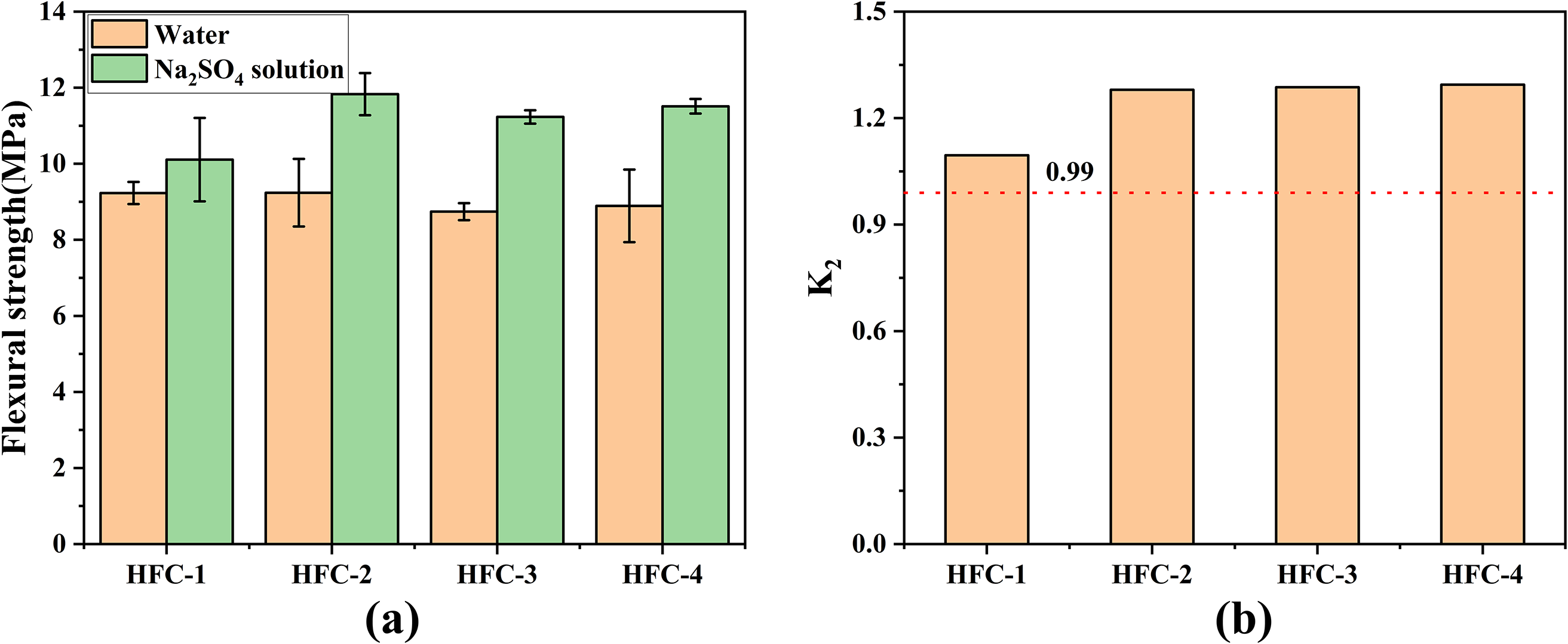
Figure 13 Sulfate resistance performance of mortar at 60 d: (a) flexural strength and (b) coefficient K2
As shown in Figure 13, the variation in flexural strength and K2 values at 60 d followed the same trend as those at 28 d, with the HFC-2 to HFC-4 pastes exhibiting higher flexural strength and K2 values than HFC-1. Notably, the HFC-3 and HFC-4 pastes showed a significant improvement compared with their 28 d performance. These results indicate that cements designed with a higher Fe-Al ratio possess superior long-term sulfate resistance, which is consistent with the findings by Wan et al. [37]. This enhancement is likely attributed to the increased formation of C2F hydration products, which exhibit stronger sulfate resistance. Their hydration produces a greater amount of FH3 gel than that generated from C4AF hydration [38], thereby enhancing the overall sulfate-resistance capability.
The appearance of HFC samples after being immersed in sulfate solution for 28 d further confirmed its excellent sulfate resistance (as shown in Figure 14). As the Fe-Al ratio increased, the surface color of the HFC shifted from light yellow to a darker tone, accompanied by smoother and denser surface precipitates. This phenomenon was primarily attributed to the enhanced formation of a compact iron oxide layer on the HFC surface with increasing iron content, which effectively inhibited the reaction between the cement matrix and sulfate ions. These observations indicate that sulfate-resistant cement can be produced using copper slag, and that increasing the Fe-Al ratio significantly enhances the long-term sulfate-resistance performance of the cement.
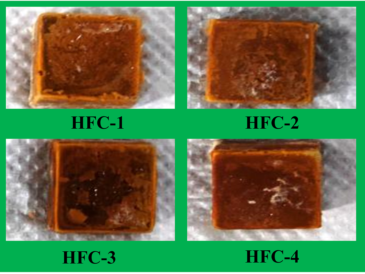
Figure 14 Images of HFC sample soaked in sulfate solution for 28 d
The spectra of the hydration products of the HFC pastes under sulfate attack are shown in Figure 15.
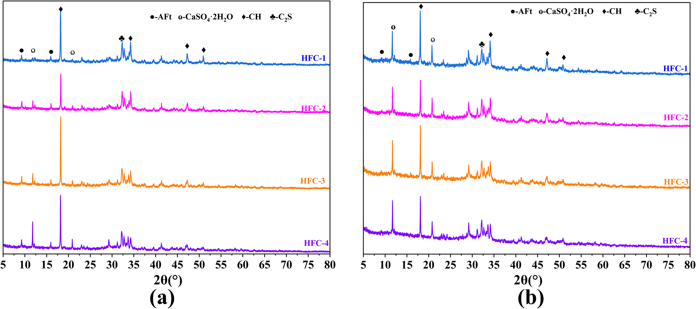
Figure 15 XRD spectra of HFC pastes in sulfate solution: (a) 7 d and (b) 28 d
As shown in Figure 15a, all HFC pastes exhibited a distinct AFt characteristic peak at 9.25°, which was attributed to the sufficient SO42− ions supplied by the Na2SO4 solution and they reacted with Ca and Al to form ettringite [39, 40]. After 28 d of sulfate attack, the HFC pastes containing higher proportions of high-iron minerals did not display an AFm characteristic peak around 9.88°. Instead, the AFt peak at 9.25° remained prominent and intensified with increasing Fe-Al ratios. Previous studies have reported that OPC pastes subjected to 28 d of sulfate attack exhibited a reduction in the AFt peak along with the appearance of a pronounced AFm peak around 9.88° [41]. These results indicate that a higher Fe-Al ratio promotes the formation of C2F, enhances the stability of AFt and inhibits its transformation into AFm, which is consistent with the findings reported by Gao et al. [18]. This mechanism explains the superior strength retention of the HFC-2, HFC-3, and HFC-4 pastes under sulfate attack. Moreover, the peak at 11.65° in the HFC pastes gradually intensified, indicating that gypsum formation dominated the reaction processes during the later stages of sulfate attack.
To better observe the microstructural evolution of the cement specimens in the sulfate solution, SEM analysis was performed on the specimens after 28 d of sulfate attack, as shown in Figure 16.
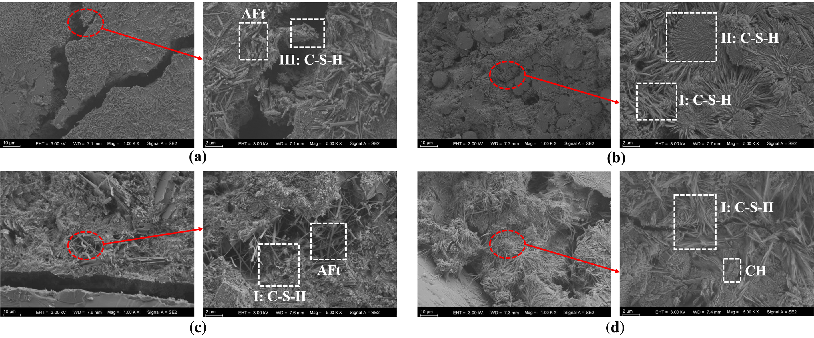
Figure 16 SEM image of HFC pastes in sulfate solution: (a) HFC-1, (b) HFC-2, (c) HFC-3 and (d) HFC-4
From Figure 16, the surfaces of the cement particles were covered with C-S-H gels exhibiting diverse morphologies, including fibrous type I, anchoring type II, and clustered type III [42]. These gels intertwined to form a continuous protective layer that bound the originally discrete cement particles and their hydration products, producing a dense and well-consolidated internal structure. Such a structure effectively restricted the penetration of the sulfate solution into the cement matrix and thus enhanced sulfate resistance. The results suggest that refinement of the microstructure and preservation of the paste–aggregate transition zone is key to the performance of cementitious systems subjected to severe environment. Similar observations were reported by Güleç and Çayır [43] for functional layered concrete exposed to 900°C, where SEM and SEM–EDX mapping showed that a denser matrix and an intact aggregate–cement interface in the calcium-aluminate-based outer layer were directly associated with improved residual strength.
Compared with the HFC-1 paste, the HFC-2, HFC-3, and HFC-4 pastes developed particularly dense networks of fibrous type I C-S-H after exposure, with the effect being most pronounced in HFC-2, where internal cracks were almost completely filled by gel-like phases. This microstructural refinement was likely associated with the higher Fe-Al ratios: iron-rich phases more readily formed a compact, adsorptive FH3 gel layer in the SO42− environment [44], which reduced calcium dissolution and hindered the diffusion of aggressive ions into the matrix. In addition, similar to the findings reported by Güleç and Çayır [43], the dense C–S–H/FH3 networks and less distinct interfaces observed in our high-Fe HFCs can be interpreted as an improved transition zone that contributes to their higher sulfate-resistance indices.
Overall, these observations indicate that lowering the relative calcium content while increasing the proportion of iron-bearing phases in HFC promotes the formation of dense C-S-H/FH3 networks, effectively suppresses harmful reactions between hydration products and SO42−, and thereby significantly enhances sulfate resistance. This approach also offers a promising strategy for the high-value utilization of copper slag in the development of high-iron, sulfate-resistant cements.
3.5 Additional discussion and limitation
Rietveld quantification showed that the fraction of C2F increased systematically from HFC 1 to HFC 4, with a concomitant reduction of C4AF and almost complete disappearance of C3A. This evolution was accompanied by a decrease in 7 d cumulative heat release (from 229.19 to 221.80 J·g−1) and a 15.74 to 22.56% reduction in 28 d compressive strength, confirming that the higher C2F content lowers overall reactivity and delays strength development. Conversely, under 3 wt.% Na2SO4, mortars with higher C2F contents exhibited higher K2 values (>0.99 at 28 d and >1.2 at 60 d) and positive strength gains relative to water curing. XRD under sulfate attack revealed a stable and even intensified AFt peak at 9.25°, without an AFm peak, while SEM showed progressively denser C–S–H/FH3 networks with increasing Fe–Al ratio. Combined with previous quantitative studies on Fe substituted AFt and FH3 [33, 34, 38–40], these results support the conclusion that the increased C2F fraction promotes the formation of Fe rich AFt and FH3, which stabilize AFt, refine the pore structure, and enhance sulfate resistance, even though they slightly reduce strength in sulfate free conditions.
XRD and SEM results as presented in this study mainly provided qualitative or semi-quantitative support for the proposed mechanism. Future work should include quantitative phase analysis (e.g., Rietveld with internal standards or TGA) before and after sulfate exposure, and complementary techniques (e.g., MIP, nanoindentation) to quantify pore structure and local mechanical properties, to provide deeper, quantitative validation of the proposed mechanism.
This study systematically investigated high-iron Portland cements (HFCs) with different Fe-Al ratios prepared using an iron-rich copper slag as the main Fe source. The effects of Fe-Al ratio on clinker calcination, hydration behavior, mechanical properties, and sulfate resistance were clarified. The conclusions were as follows:
1. The optimal calcination temperature for all HFC clinkers was 1390°C. At this temperature, clinkers showed adequate burnability (f-CaO < 1.5 wt.%), stable linear shrinkage without sticking or overburning, and good grindability. XRD/Rietveld analysis confirmed that the main mineral phases were C3S, C2S, and C4AF-C2F solid solutions, and that changing the Fe-Al ratio primarily adjusted the C4AF/C2F balance without altering the overall phase assemblage.
2. Increasing the Fe-Al ratio (i.e., increasing C2F and reducing C4AF and C3A) led to delayed hydration and reduced mechanical performance. Relative to HFC-1 (Fe/Al = 1), the 28 d compressive strength and flexural strength of higher Fe-Al mixes decreased by 15.74% to 22.56% and 9.79% to 14.69%, respectively. However, all HFC pastes still exceeded the strength requirements for low-heat cement, and the total heat release at 7 d for every mix remained below 250 kJ/kg.
3. All HFC mortars exhibited excellent sulfate resistance, which improved with increasing Fe-Al ratio. The erosion coefficient K2 remained above 0.99 at both 28 d and 60 d, while specimens with higher Fe-Al ratios showed better strength retention, darker and more uniform surface coloration, and denser surface precipitates after Na2SO4 exposure.
4. Microstructural and phase analyses indicated that higher Fe-Al ratios enhanced the stability of AFt and suppressed its transformation to AFm, while promoting the formation of a dense, cluster-like C-S-H/FH3 protective layer that restricted SO42− ingress. These results demonstrated that iron-rich copper slag can be effectively and safely used to produce low-heat, sulfate-resistant HFCs, providing a high-value utilization route for copper slag in marine and other aggressive environments.
Acknowledgement
Not applicable.
Funding Statement
This research was funded by Scientific Research and Development Project of Fujian Provincial Department of Housing and Urban-Rural Development (2025-K-40), the Natural Science Foundation of Fujian Province (2025J08069), and Educational and Scientific Research Project for Early Career Faculty in Fujian Province (JAT231023).
Author Contributions
Guanghong Lai: writing—original draft, visualization. Jian Yang: investigation, data curation, formal analysis, methodology. Jingou Chi: supervision, resources. Chunhui Luo: project administration, resources. Demei Yu: validation, supervision. Tengfei Fu: conceptualization, writing—review and editing, funding acquisition. All authors reviewed and approved the final version of the manuscript.
Availability of Data and Materials
The authors confirm that majority of the data supporting the findings of this study are available within the article. Additional data are available from the Corresponding Author, Tengfei Fu, upon reasonable request.
Ethics Approval
Not applicable.
Conflicts of Interest
The authors declare no conflicts of interest.