The mechanism of enhancing the erosion resistance of rust-cracked reinforced concrete by electrophoretic deposition repair technology
Reinforced concrete structures serve as the cornerstone of modern civil engineering, and their durability directly affects the safe operation and service life of infrastructure. However, in complex and variable service environments, the corrosion of reinforcing bars and the resulting expansion and cracking of concrete due to rust have become one of the most common and serious diseases faced by reinforced concrete structures worldwide [1–5]. The fundamental cause of steel bar corrosion lies in the disruption of the alkaline environment of concrete pores, or the penetration of external corrosive media (such as chloride ions, carbon dioxide) through the concrete protective layer to reach the surface of the reinforcing bars, destroying their passivation film, thereby initiating electrochemical corrosion. The volume of corrosion products is much larger than that of the original reinforcing bars, and their volume expansion generates a huge radial pressure. When this exceeds the tensile strength of the concrete, it will cause the concrete to crack along the direction of the reinforcing bars, forming rust expansion cracks. The appearance of rust expansion cracks provides a more direct channel for external corrosive media, forming a vicious cycle, and greatly accelerating the deterioration process of the structure [6–8].
In special environments such as high-speed railways, subways, and tramways where there are DC or AC power supply systems, the problem of stray current corrosion is particularly prominent. Stray currents can flow into or out of the reinforcing bars, disrupting the original potential balance of the bars and accelerating the corrosion and dissolution of the anode area, thereby seriously weakening the mechanical properties of the reinforcing bars and the overall durability of the structure [9–11]. Moreover, in coastal areas, sulfate and chloride salt erosion will accelerate the deterioration of the concrete protective layer [12, 13], and under the combined action of loads and cracks, the migration rate of harmful ions increases, thereby accelerating the damage and cracking rate of the internal reinforced concrete [14, 15]. Although many scholars are actively exploring the use of new materials (such as rubber fibers, nano-silica, calcium sulfate whiskers, etc.) to enhance the impermeability and ion erosion resistance of reinforced concrete [16–18], some reinforced concrete structures still inevitably suffer from rust expansion and cracking diseases due to the adverse engineering environment around them.
In the face of this severe challenge, traditional repair techniques such as surface sealing and crack grouting can only address the symptoms and are unable to fundamentally prevent the continuous corrosion of reinforcing bars and the further expansion of cracks [14–16]. Therefore, developing new repair technologies that can actively repair cracks, restore and enhance the durability of the structure has become a key scientific issue that urgently needs to be addressed in the field of civil engineering.
Although our previous studies [19–21] have optimized the process parameters for electrochemical deposition to repair rusted and cracked reinforced concrete (such as resin type, solution concentration, applied voltage, etc.), and have confirmed their feasibility in restoring mechanical properties and basic waterproofing performance, these efforts have mainly focused on the optimization of process-performance. In contrast, this research aims to address a deeper issue: to clarify the comprehensive durability improvement effect of EPD repair technology on reinforced concrete under different erosion environments, and to reveal its underlying protective mechanism.
In conclusion, although the application of electrophoretic deposition repair technology in the field of concrete restoration has shown some initial progress, the performance and mechanism of the rusted and cracked reinforced concrete after restoration in resisting various erosions, such as ions and stray currents, are still not very clear, especially in terms of resisting stray current erosion. This study aims to systematically explore the durability improvement effect of EPD repair technology on rusted and cracked reinforced concrete in different typical environments, aiming to reveal the protective mechanism of EPD repair technology in forming a physical barrier between concrete cracks/surfaces and the surface of reinforcing bars, as well as to clarify the key electrochemical mechanism for enhancing its corrosion resistance performance.
2.1 Electrophoretic deposition repair solution and preparation method for corroded and cracked reinforced concrete specimens
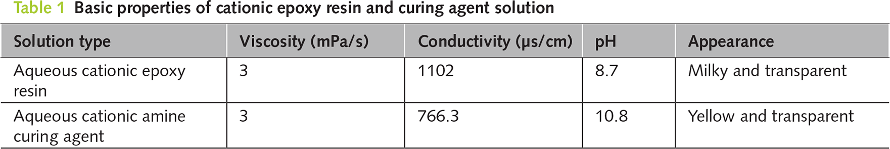
According to the method in reference [22], aqueous cationic epoxy resin and aqueous cationic amine curing agent were synthesized, respectively. A high-performance electrophoretic deposition repair solution was prepared by mixing epoxy groups and amine hydrogens in a 1:1 ratio, with a concentration of 0.1 mol·L−1. The basic properties of the two solutions are shown in Table 1. The size of the cement mortar specimens was 40 × 40 × 160 mm3. The cement was P.I 42.5 grade ordinary silicate cement. The sand was of the Chinese ISO standard, and the water was tap water. The mass ratio of cement to sand and water was 1:3:0.5. The diameter of the reinforcing bars was 6 mm, and they were embedded in the middle of the concrete. After the specimen was formed, it was cured under standard conditions for 28 days before being removed. Then, the specimen was transferred to a 5% aqueous sodium chloride solution. The steel bar was used as the positive electrode, and the stainless steel sheet was used as the negative electrode. A direct current of 0.1 A·m−2 was applied to create a rust expansion crack with a width of 0.5 ± 0.1 mm.
2.2 Electrophoretic deposition repair test method
A plastic box with dimensions of 210 × 120 × 160 mm3 was used as the container, and a graphite plate with dimensions of 120 × 130 × 5 mm3 was used as the anode. The placement method for the corroded and cracked mortar specimens is shown in Figure 1, with the cracks facing downward towards the graphite plate. After pouring the prepared repair solution into the liquid receiving box, the repair was carried out by applying an electric current with the graphite plate as the anode and the corroded reinforcing bars inside the concrete as the cathode. The electrophoretic deposition repair technology was used for the repair work in the constant voltage mode, with a voltage control of 40 V, a maximum current of 0.25 A, and the environmental temperature controlled at 20 ± 2°C. The repair time was 24 h. To ensure the repair effect, the repair solution should be prepared and used immediately. The actual repair device is shown in Figure 2.
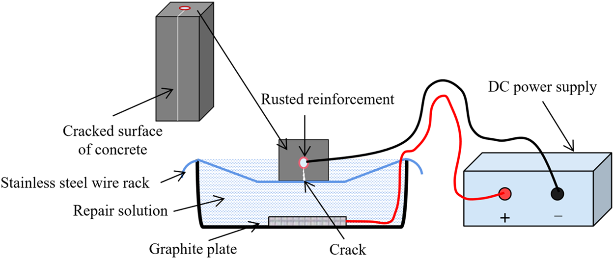
Figure 1 Schematic diagram of electrophoretic deposition repair system
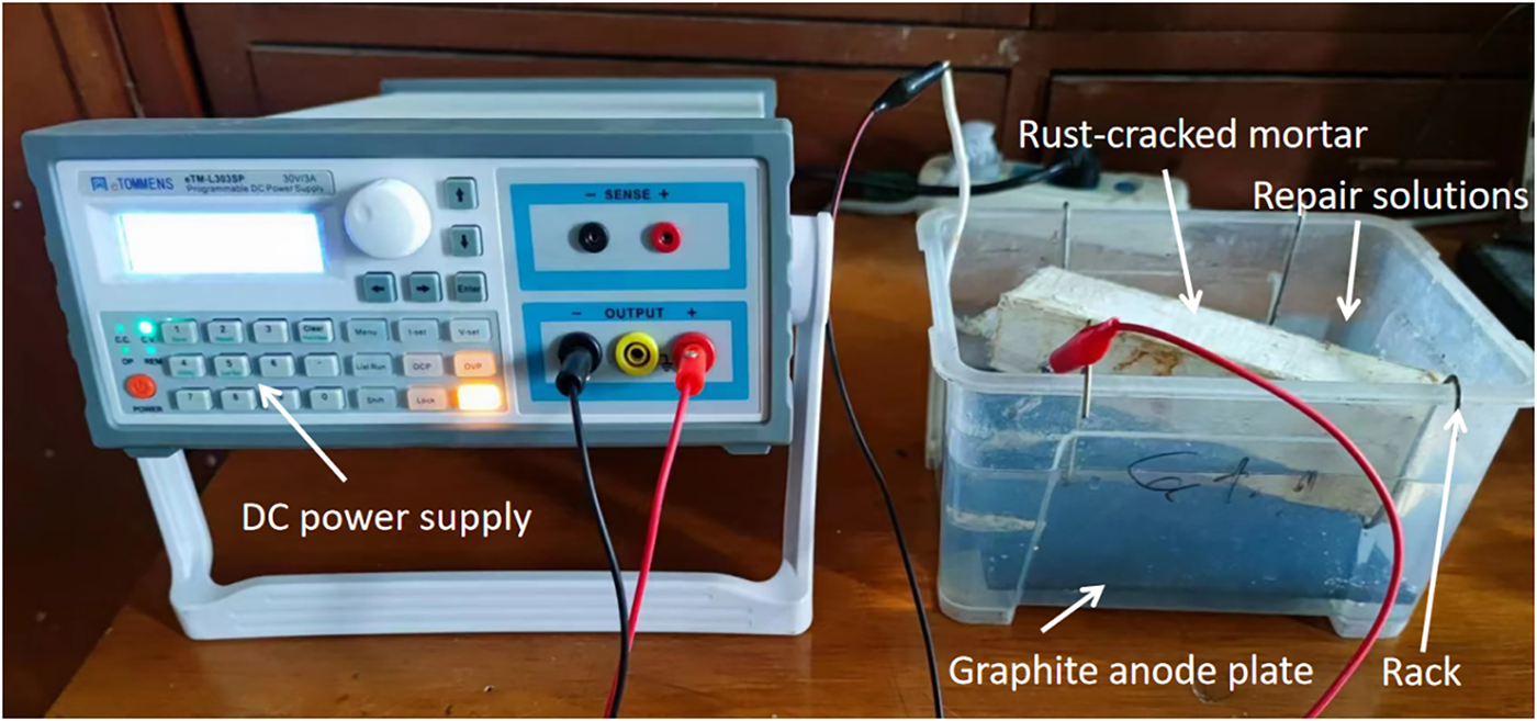
Figure 2 Electrophoretic deposition repair test device
2.3.1 Permeability resistance test
An acrylic mold with an inner diameter of 40 × 80 mm3 and a height of 540 mm was fabricated. Then, a specimen with dimensions of 40 × 40 × 80 mm3 was placed in the mold and sealed around with polyurethane glue to prevent water leakage from the sides when water was added. The mold was filled with water and the water penetration amount within the specified time was tested. The permeability coefficient can be used to characterize the water resistance ability of the specimen. The water permeation test lasted for 7 days and the precipitation height was measured using a ruler. Figure 3a, 3b shows the schematic diagram of the test device and the actual test device used. The permeability coefficient of the specimens before and after repair can be calculated according to the Darcy’s law as shown in Formula (1).
In the formula, k represents the permeability coefficient (m·s−1), Q denotes the water flow rate (m3·s−1), L is the height of the sample (m), A is the cross-sectional area (m2), and Δh is the water head difference (m).
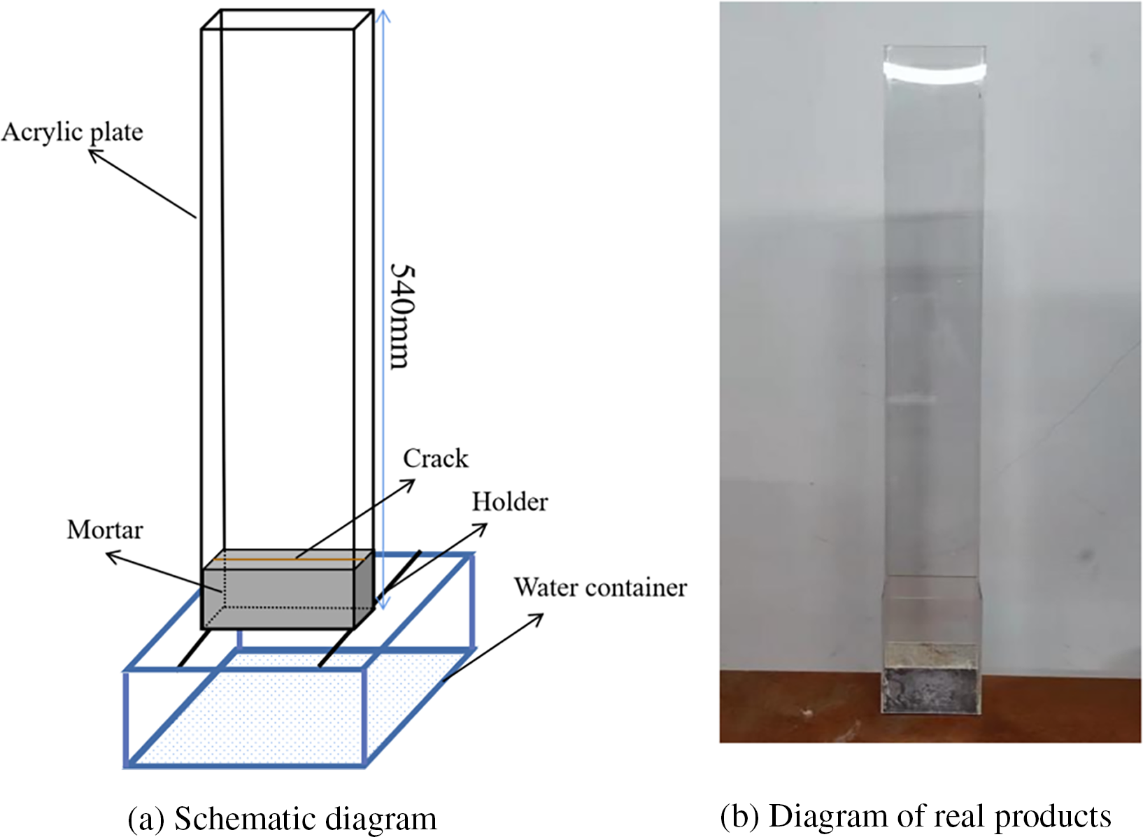
Figure 3 Water permeability test setup
2.3.2 Test of chloride ion penetration depth and sulfate ion concentration
The chloride ion penetration depth was tested using the silver nitrate colorimetric method. After a certain age period of dry-wet cycling, the penetration depth of chloride ions in different specimens was measured. The other five surfaces of the specimens were sealed with polyurethane to exclude the crack surfaces. The samples were immersed in a 5% mass fraction concentration of NaCl solution at 20°C for 12 h, then removed and allowed to dry for 12 h. One cycle lasted for 24 h. After 60 days, the specimens were split vertically along the rust expansion crack direction into two halves. The remaining powder on the fracture surface was brushed off, and 0.1 mol·L−1 silver nitrate solution was sprayed on it. The area where silver-white appeared was the chloride ion penetration zone, and the white edge was the boundary of silver chloride precipitation. The penetration depth of 6 points in each group was taken as the experimental value of the specimen, and the average value of the three specimens was taken as the chloride ion penetration depth value.
After the specimen is formed and cured, it is transferred to a 5% mass fraction concentration Na2SO4 solution for soaking for a certain period of time. Then, it is taken out of the erosion solution. The mortar is dried to a constant weight in an oven at a temperature of 50°C. Using a cutting machine, the specimens are ground layer by layer according to the standard layering grinding method. The depth of each grinding layer is set at 0–3 mm, 3–6 mm, 6–9 mm, 9–12 mm, and 12–15 mm. The powder removed from each layer is collected, then screened through a standard sieve (200 mesh) and stored in an airtight bag for later use. In this experiment, the ion chromatography analysis method is used to test the concentration of sulfate ions, and the instrument model used is ICS-1100.
2.3.3 Anti-interference current erosion performance test
Using non-destructive specimens, cracked specimens and electroplated repair specimens (which were fabricated by splitting and re-adhering after being subjected to splitting, and not through electrochemical corrosion, with all the initial specimens having new smooth reinforcing bars inside), the anti-interference current erosion performance test was conducted. The test device is shown in the figure. The specimens were placed on both ends of the liquid holding box with stainless steel plates, and a 0.05% sodium chloride solution with a mass fraction concentration was poured in and then electricity was applied. The test used direct current, with the maximum voltage and current controlled at 90 V and 1 A, respectively. The test duration was 3 days. Based on the design principles of stray current erosion acceleration tests and the previous preliminary experiments [11, 23], in this experiment, we set the DC voltage to 90 V, the chloride ion concentration to 0.05%, and the duration to 72 h.
Figure 4 shows the schematic diagram of the interference current erosion test. After the test, the specimens were split and the corroded reinforcing bars were removed. They were then immersed in a 10% hydrochloric acid solution for 48 h before being taken out and weighed to calculate the wire density of the reinforcing bars. The calculation formula for the wire density (2) is as follows:
In the formula, λ represents the linear density (g·mm–¹), M denotes the mass of the steel bar (g), and L indicates the length of the steel bar (mm).
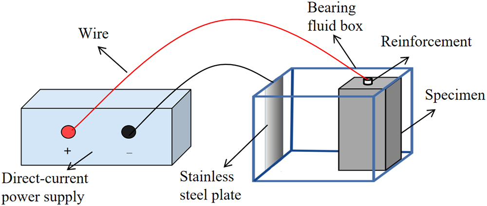
Figure 4 Schematic diagram of leakage current erosion test
2.3.4 Half-cell potential method
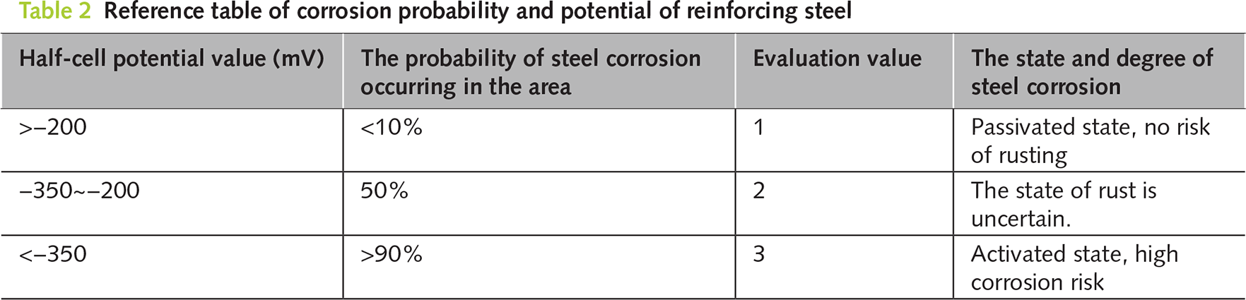
This method utilizes the electrochemical reaction of steel corrosion in concrete to cause a change in potential, thereby determining the corrosion state of the steel. Based on the standard of the American Society for Testing and Materials (ASTM C876), the potential value of the copper-copper sulfate electrode (CSE) used as the reference electrode is taken as the basis for the degree of corrosion. By measuring the potential difference reflected by the system formed between the reference electrode on the surface of the reinforced concrete and the concrete, the corrosion state of the reinforcing bars is evaluated. The potential testing system is shown in Figure 5. To comprehensively reflect the distribution of steel corrosion, points need to be evenly distributed on the surface of the concrete specimen. Each measurement point is uniformly arranged every 20 mm along the specimen. After placing the reference electrode stably at the measurement point, wait for 30–60 s. When the reading of the multimeter fluctuates ≤2 mV, record the potential value (usually record 3 times and take the average to reduce accidental error), and evaluate according to the reference standard shown in Table 2.
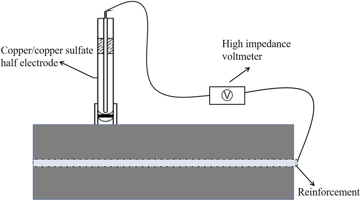
Figure 5 Potential testing system
X-ray computed tomography is a non-destructive testing technique used in industry or research, similar to medical CT scanning, which can be used to detect internal defects in materials. It is abbreviated as X-CT or XCT. The tomographic images obtained through scanning can reflect the structural level, material condition, defect cracks, and other internal conditions of the selected layer. Using the Y. CTPrecisionS X-ray CT scanner (YXLON, Germany). The working voltage of the X-ray tube is 195 kV and the current is 0.34 mA. In this experiment, the internal planar layers of specimens at distances of 2, 7, 12, and 17 mm from the surface of the crack were scanned and photographed, respectively.
2.3.6 Detailed microscopic morphology observation method
The microscopic morphology was observed using the Bada Tong bench-top high-definition industrial CCD video microscope (wide-angle lens, 60 frame output, 4800 W pixel microscope). The magnification range of this instrument is 21–135 times. The corresponding position of the sample was placed under the microscope lens, and the appropriate imaging conditions were found by adjusting the focal length and the brightness of the illumination light. The microscopic morphology of the sample was analyzed using a scanning electron microscope (SEM; ZEISS Gemini 300) at an acceleration voltage of 30 kV.
3.1 The erosion resistance performance of the specimens after electrophoretic deposition treatment
3.1.1 The anti-ion erosion and anti-permeation performance of the specimens after electrophoretic deposition repair
Figure 6 shows the chloride ion penetration depths of the unrepaired specimen (P-UR), the specimen without cracking (P-UC), and the repaired specimen (P-R) after 60 days of corrosion. As can be seen from the figure, the penetration depths of P-R, P-UR, and P-UC specimens after 60 days of chloride ion erosion are 2, 16, and 13 mm, respectively. This indicates that the anti-chloride ion penetration performance of the specimens after electrophoretic deposition repair has significantly improved. The anti-chloride ion penetration performance of the P-R specimen after repair is even better than that of the P-UC specimen, with the penetration depth being only 15.4% of that of the P-UC specimen. Figure 7 shows the changes in the concentration of sulfate ions in different layers of each specimen after 12 months of sulfate erosion. From the figure, it can be seen that the concentration of sulfate ions in the mortar is higher the closer it is to the surface of the specimen. At a distance of 3 mm from the surface, the concentration of sulfate ions among the P-R, P-UR, and P-UC specimens is the greatest, being 5.25, 9.92, and 23.84 mg·g−1, respectively. As the sampling depth increases, the difference in sulfate ion concentration among the three specimens decreases, but the order of concentration remains P-UC > P-UR > P-R. The results show that the anti-chloride and anti-sulfate ion erosion performance of the original rust-expanded and cracked specimens will be significantly improved after electrophoretic deposition repair, and the anti-sulfate ion erosion performance of the repaired specimens is better than that of the un-cracked specimens.
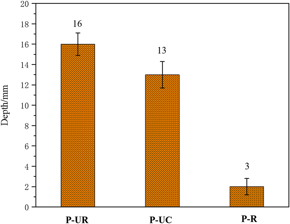
Figure 6 The chloride ion penetration depth of each specimen
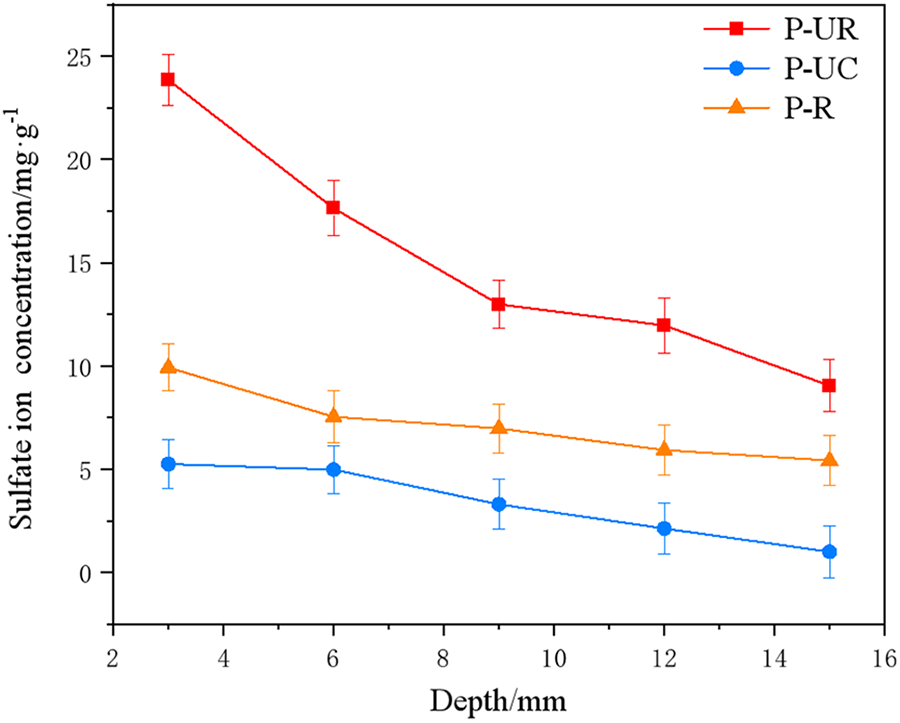
Figure 7 Concentration of sulfate ions at different depths
Figure 8 shows the changes in water seepage volume of each specimen within 30 days. As can be seen from the figure, throughout the entire testing period, the water seepage volume of P-UR was the largest, followed by P-UC, and P-UR was the smallest. On the 30th day of the test, the maximum water seepage volumes of the P-R, P-UR, and P-UC specimens were 65, 132, and 28 kg·m−2, respectively, and the permeability coefficients were 0.166, 0.337, and 0.072, respectively. Compared with P-UR, the anti-seepage performance of the P-UR specimen after 24 h of electrophoretic deposition repair was significantly improved, and even its anti-seepage performance was better than that of P-UC.
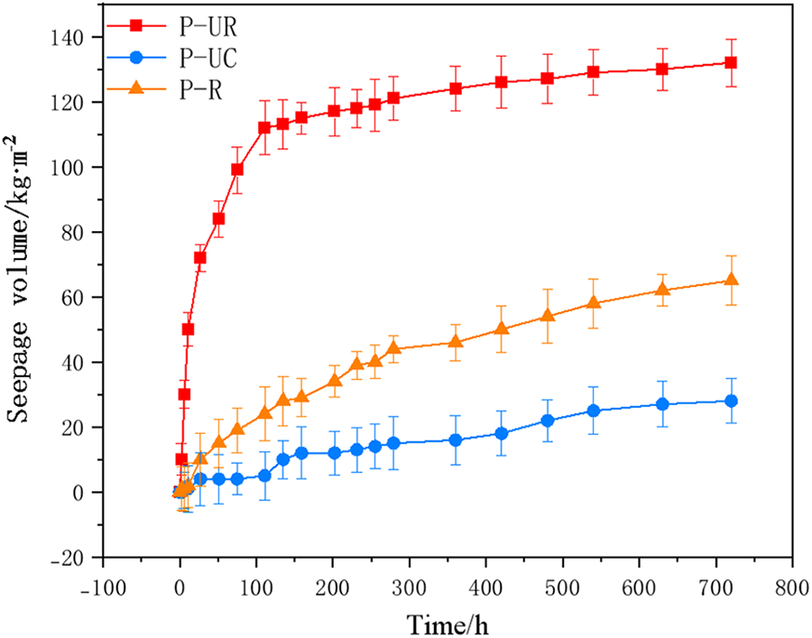
Figure 8 Changes in seepage water volume of each specimen
The research results show that electrostatic deposition repair can enhance the impermeability of rusted and cracked reinforced concrete. After the repair, the impermeability of the test specimens is even better than that of the P-UC specimens. Generally, corrosive ions erode reinforced concrete structures through water as the medium. Therefore, it can be concluded that the improvement of the anti-ion erosion performance of the repaired reinforced concrete is mainly related to the improvement of its impermeability. Literature [24–26] indicates that after electrostatic deposition repair, epoxy resin will deposit in the cracks and on the surface of the test specimens. The epoxy resin film deposited on the mortar surface is very dense and can effectively prevent water from contacting the mortar matrix, thus effectively delaying the penetration of erosive ions into the concrete interior.
3.1.2 The anti-interference current erosion performance of the specimens after electrophoretic deposition repair
Figure 9 shows the corrosion morphology of different specimens after simulated stray current erosion. As can be seen from the figure, when the specimens have cracks, the internal reinforcement of P-UR suffers severe corrosion after 72 h of continuous stray current erosion, and its integrity is severely damaged. At the same time, it can be observed from the figure that the reinforcement surface of P-UC specimens also undergoes corrosion after stray current erosion, but only a small amount of rust appears on the surface. After 24 h of electrophoretic deposition repair, when the specimens were subjected to stray current erosion again, the surface of the reinforcement still remained smooth and bright, similar to the state at the time of pouring. Figure 10 shows the linear density of the reinforcement after stray current erosion for each specimen, ranked in order of size as P-R > P-UC > P-UR, which are 0.188, 0.166, and 0.159 kg·m−1, respectively. Among them, the linear density of the reinforcement in the P-R specimen is extremely close to that of the standard sample (0.191 kg·m−1), approximately 98% of the standard sample. The research results show that electrophoretic deposition repair technology can significantly improve the resistance of reinforced concrete to stray current erosion.
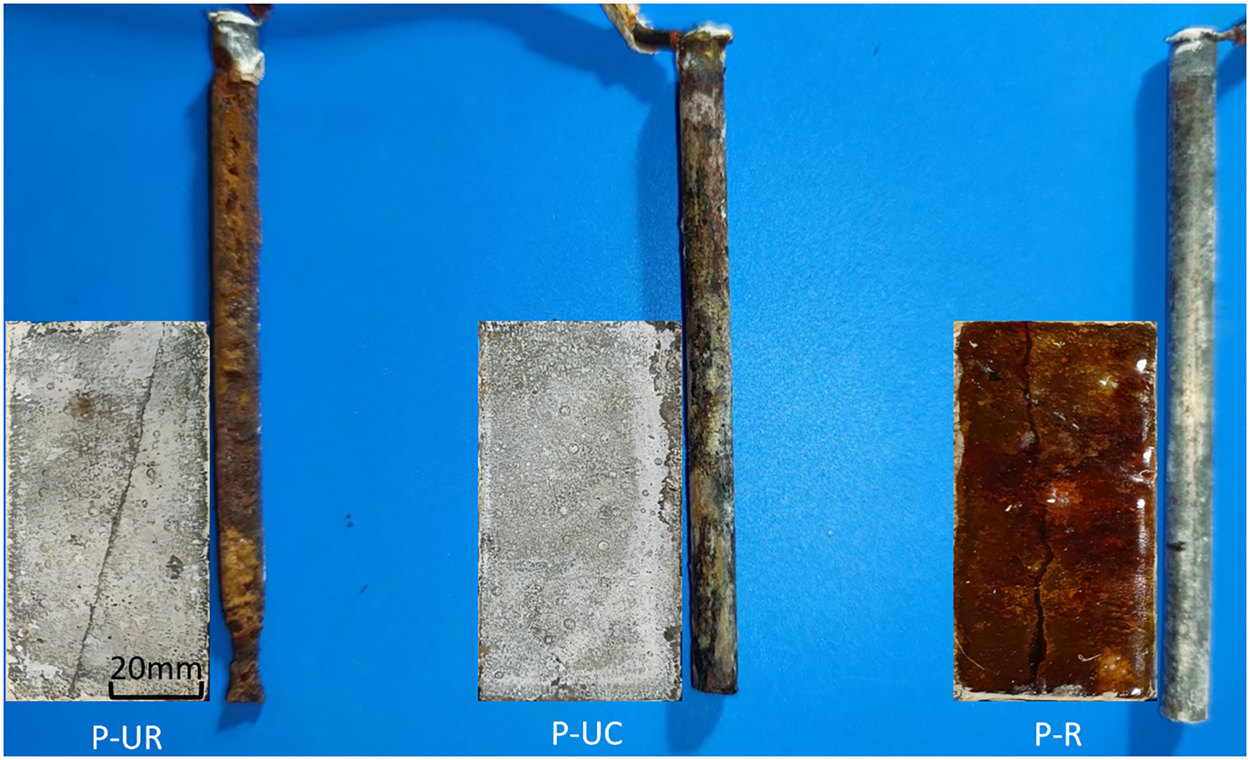
Figure 9 Morphology of reinforcing bars in each specimen after stray current erosion
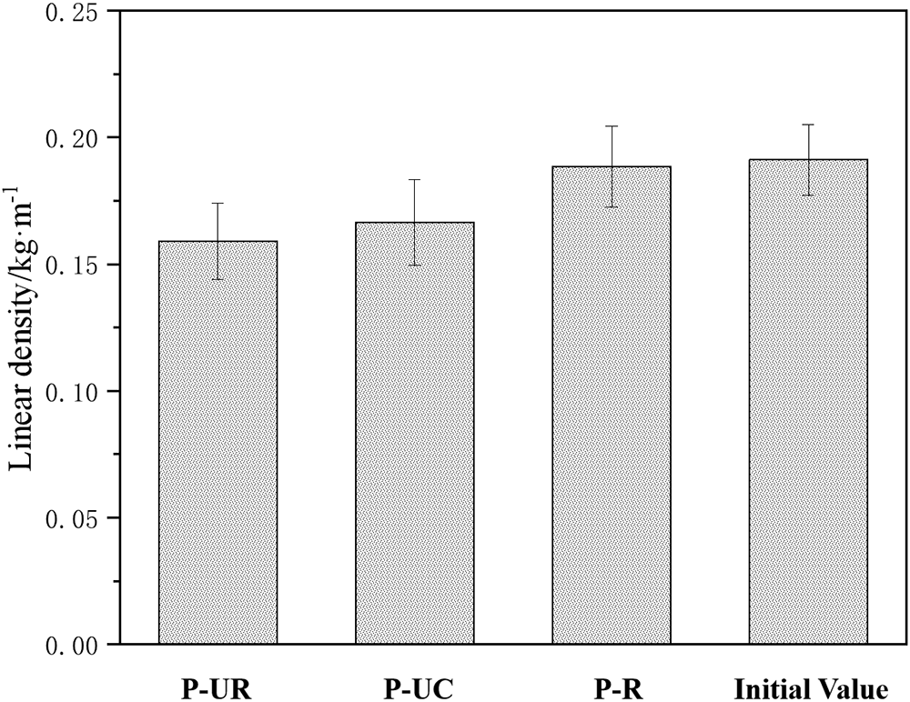
Figure 10 Linear density of different reinforcing bars
3.2 Electrochemical characteristics of reinforcing bars after electrophoretic deposition repair
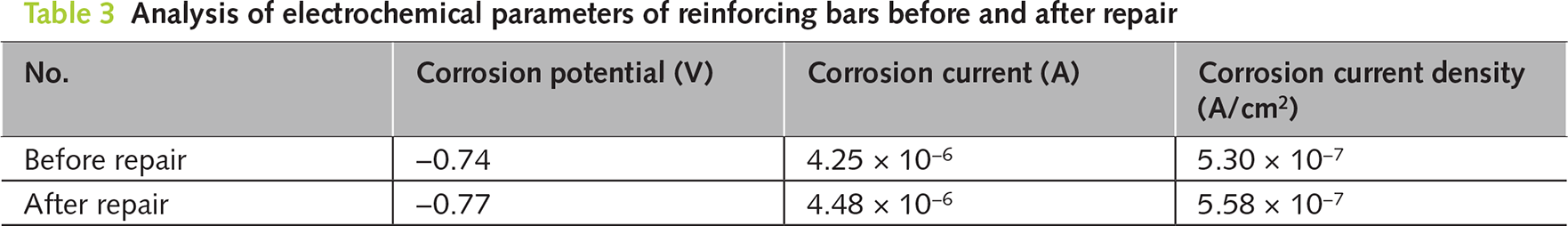
Figure 11a, 11b respectively shows the Nyquist plots and Tafel polarization curves of the internal reinforcing bars before and after the repair. The larger the radius of the capacitor ring, the better the corrosion resistance of the reinforcing bars. As can be seen from the figure, the radius of the capacitor ring of the internal reinforcing bars in the electrophoretic deposition-repaired specimen was much larger than that of the reinforcing bars in the P-UR specimen. Table 3 shows the corrosion potential, corrosion current, and current density calculated based on the Tafel curve fitting. The higher the corrosion potential, the better the corrosion resistance of the reinforcing bars. Before the repair, the corrosion potential of the reinforcing bars was −0.77 V, and the corrosion ion density was 5.58 × 10⁻⁷ A·cm−2. After the repair, it rose to −0.74 V, and the corrosion current density decreased to 5.30 × 10⁻⁷ A·cm−2. From the chart, it can be seen that the corrosion potential of the reinforcing bars after electrophoretic deposition repair has increased, indicating better corrosion resistance.
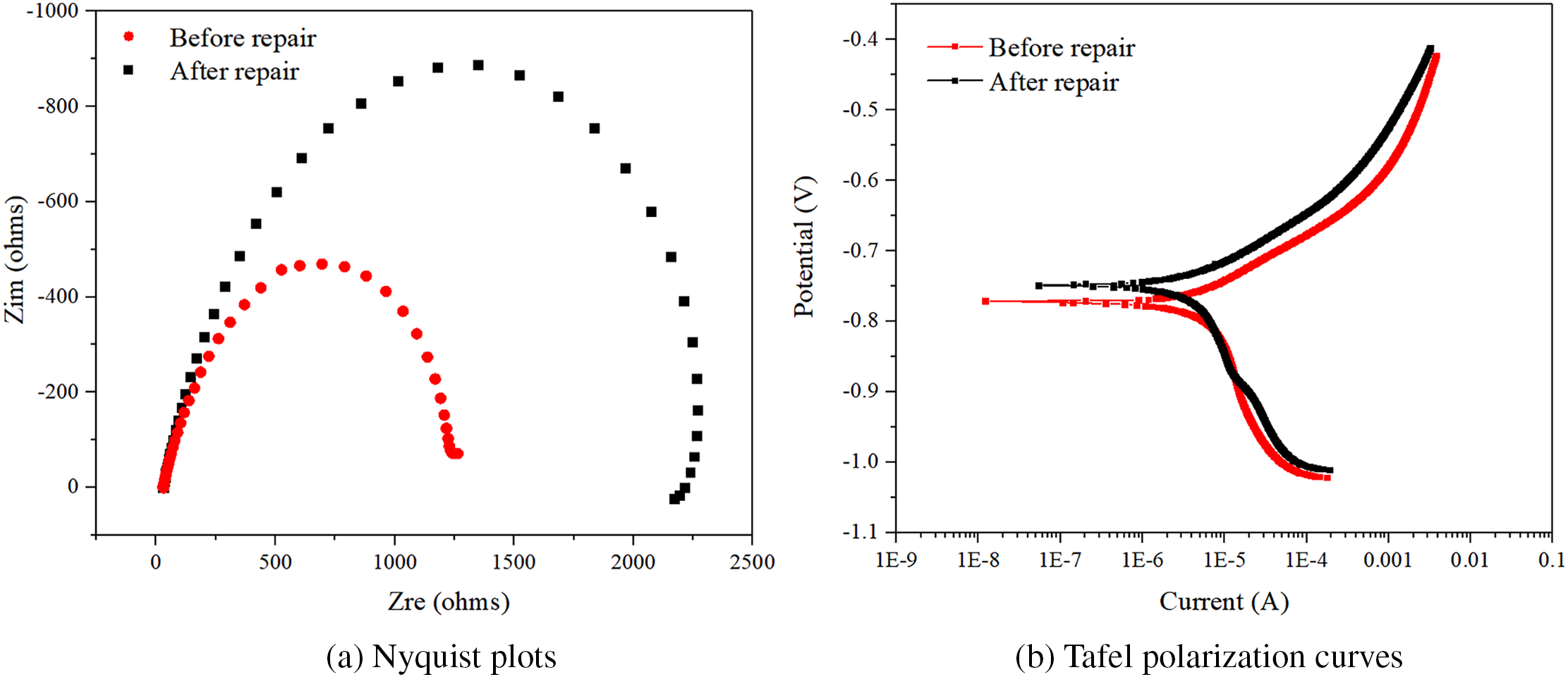
Figure 11 Nyquist plots and Tafel polarization curves of the reinforcing bars before and after repair
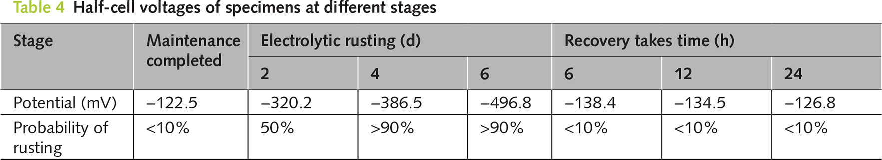
The semi-cell potential method can determine the relative value of a reinforcing bar compared to the reference electrode by comparing the potential difference between the reference electrode and the measured metal. From Table 2, it can be seen that if the relative value was high, it indicates a higher probability of steel corrosion. Conversely, if the relative value was low, it suggests a lower probability of possible corrosion of the reinforcing bar. Through this monitoring method, we can indirectly understand whether the probability of the original corroded reinforcing bar continuing to corrode after electroplating deposition can be reduced. Table 4 summarizes the changes in the average relative potential of the internal reinforcing bars during the process from curing completion to the manufacture of the corroded concrete and then to electroplating deposition repair. From the table, it can be seen that after the curing was completed, the semi-cell potential of the un-electrified corroded reinforcing bar was −122.5 mV. According to Table 2 (Reference Table for the Relationship between Steel Corrosion Probability and Potential), at this time, the corrosion probability of the reinforcing bar was extremely low, less than 5%. This is because the pH value around the reinforcing bar is high, there were no chloride ions inside, and it was not eroded by current. Later, the specimen was placed in a salt solution and the reinforcing bar was subjected to an anode current to manufacture the rusted cracks. It can be seen that after 2 days of electrified corrosion, the semi-cell potential of the reinforcing bar decreased significantly to −320.2 mV, and the corrosion probability of the reinforcing bar increased to 50%. As the electrified corrosion time further increased, the semi-cell potential of the reinforcing bar dropped to −496.8 mV after 6 days of electrified corrosion, and the corrosion probability was greater than 90%. At this time, the width of the rusted cracks in the mortar was approximately 0.5 mm. When an anode current was applied to the reinforcing bar, the iron atoms in the steel lose electrons rapidly and react with oxygen to form iron oxide. Meanwhile, the chloride ions entering the specimen from the interior will disrupt the local potential balance of the reinforcing bar and accelerate its corrosion. After 6 h of electroplating deposition repair, the semi-cell potential of the reinforcing bar increased to −138.4 mV, and the probability of further corrosion of the reinforcing bar decreased significantly to 10%, and it returned to 10% after the repair time was extended. This result indicates that the potential value inside the reinforcing bar will increase after electroplating deposition repair, which may be related to the regeneration of the passivation film and the deposition of epoxy resin on the reinforcing bar.
The research results show that the significant improvement in the anti-interference current erosion performance of reinforced concrete through electrophoretic deposition repair technology was related to both the cracks and the epoxy resin insulation materials deposited on the surface (as shown in the morphology diagram of P-R specimens in Figure 10), and to the increase in the corrosion potential of the reinforcing bars. Literature [21, 25] indicates that the cured epoxy resin provides excellent sealing properties, which can help maintain the dryness of the concrete and increase the resistance of the concrete. Moreover, the epoxy resin itself has excellent insulation properties, which can further enhance the overall resistance of the repaired reinforced concrete. The higher the resistance, the stronger the ability of the reinforced concrete to resist interference with current erosion. According to the research results of this paper, after the negative electrode was applied to the reinforcing bars, the corrosion potential of the reinforcing bars increases, and the corrosion probability significantly decreases.
3.3 The filling morphology of concrete cracks after electrophoretic deposition repair
Figure 12 shows the different CT scan layer positions of the specimen after 24 h of electrophoretic deposition repair. Figure 13, on the left, presents the microstructure of the specimen at different crack depth layers, while the single image on the right shows the cross-sectional morphology of the specimen. The porous areas with darker gray are concrete, and the black areas are pores (cylindrical) or cracks (linear). From the figure, it can be seen that the epoxy resin (the pale gray shaded part in the figure) fills the upper cracks relatively densely, with few remaining spaces, and a clear epoxy resin film deposition layer was formed at the top of the specimen crack surface (within the yellow dotted line in the figure). As the depth increases, the deposition amount of epoxy resin in the cracks decreases. This may be related to two factors: (1) The deeper the crack, the fewer the number of cationic epoxy resin and curing agent molecules inside. (2) The width of the internal cracks is smaller, and it is more difficult for molecules to penetrate into the interior, so the filling effect of cracks near the reinforcing bars was worse than that of the surface cracks. The research results show that: The longer the repair time within 24 h, the greater the depth of epoxy resin filling. Compared with the later stage of repair, the epoxy resin filling depth of the repair in the early stage was faster, and the surface cracks were the easiest to be filled densely, while the filling effect of the inner layer cracks was relatively poor. Although the cracks are not completely filled densely, the epoxy resin protective layer on the crack surface and the epoxy resin in the cracks can effectively prevent the migration of erosion media (such as chloride ions, sulfate ions) to the interior, significantly improving the anti-erosion performance of the electroplated deposited repaired concrete.
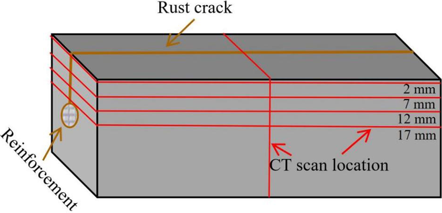
Figure 12 Illustration of CT scan layers
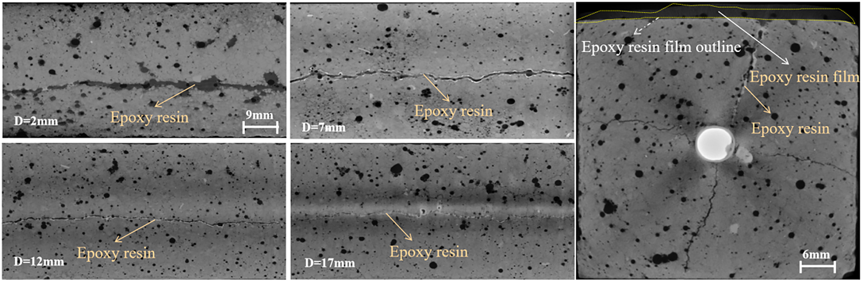
Figure 13 CT scan morphology of different depth layers and sections of the specimen
Figure 14 shows the morphology of the interface between the corroded reinforcing bars and the epoxy resin inside the repaired specimen. Figure 14a shows the interface morphology between the corroded reinforcing bars and the concrete after splitting. From the figure, it can be seen that there is a yellowish-brown epoxy resin filling at the defect areas between the reinforcing bars and the concrete. Figure 14b shows the microscopic morphology of the corroded reinforcing bars after repair, and from the figure, it can be seen that a transparent epoxy resin protective layer was attached to the surface of the electroplated-repaired corroded reinforcing bars. Thus, it can be known that the epoxy resin protective layer attached to the surface of the corroded reinforcing bar was an important reason for the improvement of the reinforcing bars’ resistance to chloride ion and stray current erosion, and the reduction of the corrosion potential caused by electrochemical repair enhances this anti-erosion ability.
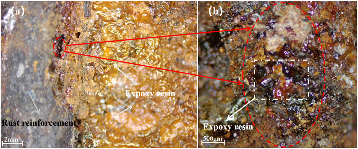
Figure 14 Microscopic morphology of the interface section between reinforcing bars and concrete after repair
Figure 15a,b shows the surface morphology of corroded reinforcing bars. From the figures, it can be seen that the rust layer on the surface of the reinforcing bars has a porous structure, which is loose and prone to cracking and detachment. Figure 15c,d shows the surface morphology of the corroded reinforcing bars after repair. From the figures, it can be seen that after repair, the epoxy resin will fill and encapsulate the corroded rust layer, bonding it into a whole to prevent its detachment. Thus, it can be seen that the epoxy resin deposited after electrophoretic deposition repair can closely adhere to the surface of the reinforcing bars, closing the potential transmission paths of the erosion medium caused by rust, thereby further preventing the continuous rusting of the original corroded reinforcing bars after repair. The deposition of epoxy resin on the surface can also restore the adhesion force between the original corroded reinforcing bars and the concrete on another level [26]. Our previous studies on the microscopic structure of the interface also indicated that the electrophoretic coating (epoxy resin) could form a good mechanical connection with the corroded reinforced concrete, with a tight interface bond and no layering problem [27]. Through this research, we confirmed that the epoxy resin could smoothly penetrate and anchor in the loose and porous rust layer structure, forming a tight mechanical interlock with the rust layer, thereby ensuring the bonding stability of the rust crack interface.
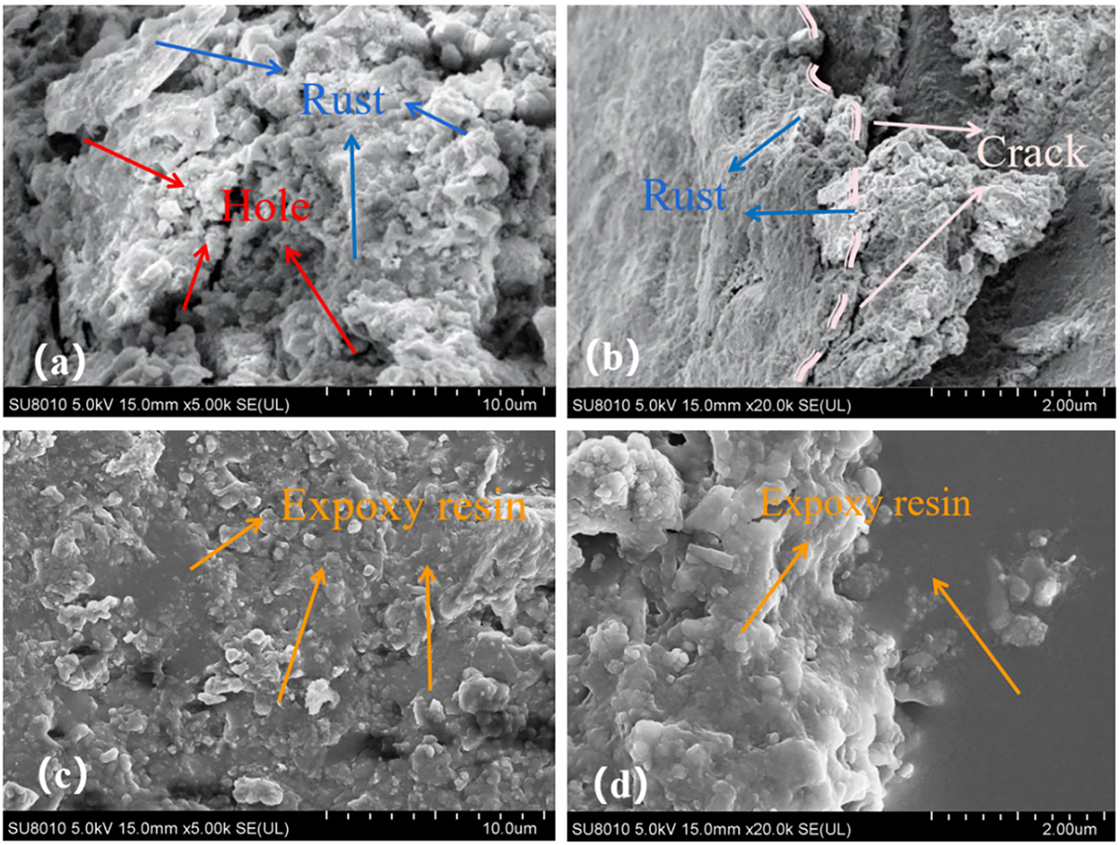
Figure 15 Microscopic morphology comparison of the corroded reinforcing bars surfaces before and after repair
The results of this study indicate that electrophoretic deposition (EPD) repair technology can significantly enhance the corrosion resistance of reinforced concrete through multiple synergistic mechanisms. It is important to note that the protection principle of EPD repair technology is fundamentally different from that of traditional cathodic protection (CP) technology. Cathodic protection achieves this by applying a continuous external current, causing the steel reinforcement to maintain a continuously polarized state at the corrosion-resistant zone, thereby completely preventing the occurrence of the corrosion reaction thermodynamically [27–29].
Unlike traditional cathodic protection (CP) techniques that rely on continuous external current for electrochemical intervention, the electrophoretic deposition (EPD) repair technology adopted in this study represents a comprehensive strategy that combines active repair with long-term protection. Its outstanding anti-erosion ability is not due to the continuous input of external energy, but rather the multiple synergistic barrier effects established within the system during the repair process.
This study also indicates that the protective efficacy provided by the EPD repair technology exceeds that of traditional crack repair methods. Compared with the polymer injection method, the latter mainly passively fills macroscopic cracks through pressure, and its protective effect is limited to physically sealing the cracks. The implementation period of this method is usually 1–3 days [30, 31]. The electrochemical deposition method (such as electrodialysis technology) utilizes the electric field to drive the migration of inorganic ions like calcium and magnesium, forming carbonate or hydroxide deposits near the cathode to fill the cracks [32–34]. However, the implementation period of this method is usually several weeks. These deposits are inorganic salts, usually porous and of low strength, and their main function is to block the cracks, with limited direct protection for the reinforcing bars.
In contrast, the EPD repair technology implements an efficient and comprehensive “repair-protection” integrated strategy. Its protective effect stems from a complete mechanism chain from the active repair process to the passive barrier state: During the repair process, the electric field actively drives cationic repair molecules to migrate and deposit towards the cathode (reinforcing bars), and the accompanying cathode reaction simultaneously improves the electrochemical environment at the reinforcing bar interface; after the repair is completed, a final barrier state providing long-term durability is formed—that is, the cured epoxy resin constructs a dense, insulating continuous film on the concrete cracks and the surface of the reinforcing bars.
This unique mechanism enables EPD repair technology to integrate and surpass the advantages of traditional methods: not only does it possess the excellent physical barrier capability similar to the polymer injection method, but it also endows the system with an outstanding resistance enhancement effect to resist stray currents, which is incomparable to electrochemical deposition methods. Ultimately, within a short 24-h period, EPD repair technology achieved the filling of cracks, direct coating protection of reinforcing bars, and active improvement of the interface environment, demonstrating significant comprehensive advantages. Therefore, EPD repair technology integrates the advantages of physical sealing and electrochemical repair, and to a certain extent, overcomes the limitations of some traditional methods such as limited protection range or poor protective layer performance, thus becoming one of the effective repair strategies for comprehensively treating concrete cracks and steel bar corrosion.
Specifically, its protection mechanism mainly manifests in the following three aspects:
Firstly, there is the physical barrier effect. The epoxy resin forms a dense and continuous isolation film within the concrete cracks, on the structural surface, and at the most critical interface between the reinforcing bars and the concrete. This film effectively blocks the transmission paths of corrosive media such as water, oxygen, and chloride ions, fundamentally cutting off the material basis for the corrosion reaction to occur.
Secondly, there is the effect of resistance enhancement. The deposited epoxy resin, as an excellent insulator, significantly increases the resistance of the concrete protective layer and the surface of the reinforcing bars. This characteristic greatly increases the circuit resistance of the macro-battery and micro-battery corrosion, thereby inhibiting the flow of corrosion current. This also explains the mechanism behind the significant improvement in the resistance to stray current erosion of the repaired specimens, as the higher system resistance can effectively prevent the inflow and outflow of stray current.
Finally, we come to the improvement of the electrochemical environment. The EPD repair technology process itself is a cathodic process. As shown in the electrochemical test results in Section 3.3, this process causes a significant positive shift in the corrosion potential of the reinforcing bars and a decrease in the corrosion current density. This is mainly attributed to the cathodic reaction consuming H2O and O2 within the system and enriching OH− at the interface region on the steel bar surface, thereby increasing the pH value of the local pore fluid and facilitating the repair and stabilization of the damaged passivation film. From the electrochemical thermodynamic and kinetic perspectives, this reduces the corrosion tendency of the reinforcing bars.
In summary, the protective effect of EPD repair technology stems from a complete mechanism chain from the active repair process to the passive barrier state. During the repair process, the electric field drives the directional migration of cationic resins towards the cathode (reinforcing bars), and the accompanying cathode reaction temporarily improves the chemical environment at the interface of the reinforcing bars. However, the core for providing long-term durability lies in the final barrier state formed after the repair: namely, the dense and insulating barrier constructed by the cured electrophoretic deposit on the concrete cracks and the surface of the reinforcing bars. This physical barrier fundamentally endows the repaired structure with excellent resistance to ion and stray current erosion by blocking the erosion medium (physical barrier mechanism) and significantly increasing the system resistance (resistance enhancement mechanism). The EPD repair technology, through the synergistic effects of physical isolation, resistance enhancement, and environmental improvement, mainly significantly inhibits and even blocks the corrosion process at the kinetic level, providing a novel and efficient solution for the performance restoration and long-term durability guarantee of corroded reinforced concrete structures.
In this study, a control group consisting of unrepaired specimens and uncracked specimens was set up to investigate the effect of electroplating deposition repair on the resistance to ion and stray current erosion of rusted and cracked reinforced concrete specimens, and to analyze the related influencing mechanisms. Based on the experimental phenomena and analysis of this study, the following conclusions are mainly drawn:
(1) Electrodeposition repair technology can significantly enhance the impermeability of the specimens. Since erosive ions usually migrate through water as the medium, the resistance to chloride and sulfate ion erosion of the specimens after repair also increases accordingly. This is mainly attributed to the dense deposition of epoxy resin on the surface and in the cracks of the specimens, which forms an effective physical barrier layer.
(2) Electrodeposition repair technology can significantly enhance the resistance of the specimens to stray current erosion, and its effect is even better than that of specimens without cracks. This is not only because the deposition of epoxy resin in the cracks and on the surface increases the resistance of the concrete system, but more importantly, it forms an insulating protective layer on the surface of the reinforcing bars, blocking the path of stray currents.
(3) After electrodeposition repair, the corrosion potential of the internal reinforcing bars significantly shifts positively, and the corrosion probability is greatly reduced. This indicates that this repair technology not only physically isolates the erosive medium but also actively improves the corrosion state of the reinforcing bars at the electrochemical level, making them tend to be stable.
In conclusion, the core value of this study lies in revealing the synergistic mechanism of physical barrier effect, resistance enhancement effect, and electrochemical environment improvement of electrodeposition repair, providing an efficient, active, low-loss, and long-lasting repair method for corroded reinforced concrete.
Although this study has confirmed the outstanding efficacy of the electrophoretic deposition repair technology in enhancing the resistance of reinforced concrete to ion and stray current erosion, there are still some limitations that need to be further explored in future work. This study was mainly conducted in an accelerated laboratory environment, and the long-term durability of this technology under actual natural exposure conditions and complex load coupling still requires continuous verification. Additionally, the protective mechanism of EPD repair technology lies in establishing a high-resistance barrier to long-term inhibit (rather than forcibly stop) the corrosion process. Therefore, its ability to completely terminate existing corrosion, the long-term stability after the epoxy resin barrier is in service, and the protective efficacy in extremely harsh environments are the directions that need to be focused on and studied in the future. Comparing the repair effect of EPD repair technology with the long-term performance of traditional electrochemical technologies such as cathodic protection will also have significant scientific and engineering significance.
Acknowledgement
Thanks to the National Natural Science Foundation of China for the funding. Thanks to the colleagues in the laboratory for their discussions and assistance during the experiments. The authors extend their gratitude to Congfeng Zhong (from Scientific Compass www.shiyanjia.com) for providing invaluable assistance with wire-electrode cutting test.
Funding Statement
The authors are grateful to the financial supports from the National Natural Science Foundation of China (52278236, 52578264), Distinguished/Excellent Young Scientists Project of Universities in Anhui province (2022AH020026, gxyqZD2022057), Scientific research project of colleges and universities in Anhui Province (2024AH040036), The Outstanding Project of Jianghuai Talent Development Plan in Anhui Province.
Author Contributions
Yueming Wang: Methodology, data curation, writing—original draft, writing—reviewing and editing. Han Wu: Writing—reviewing, formal analysis, investigation. Baoan Zhang: Conceptualization, methodology. Zhicheng Bai: Supervision. Kaiwei Liu: Supervision. Aiguo Wang: Supervision. Daosheng Sun: Supervision. Jiawen Zhang: Data curation. Zhanyu Xu: Data curation. All authors reviewed and approved the final version of the manuscript.
Availability of Data and Materials
All the data and materials used in this study can be obtained from the corresponding authors upon reasonable request.
Ethics Approval
Not applicable.
Conflicts of Interest
The authors declare no conflicts of interest.